46230809.pdf - 第10页
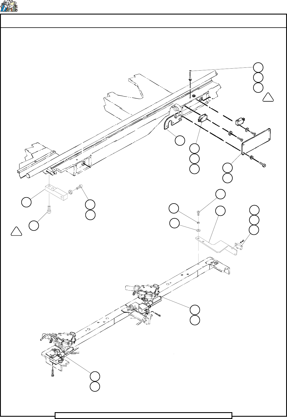
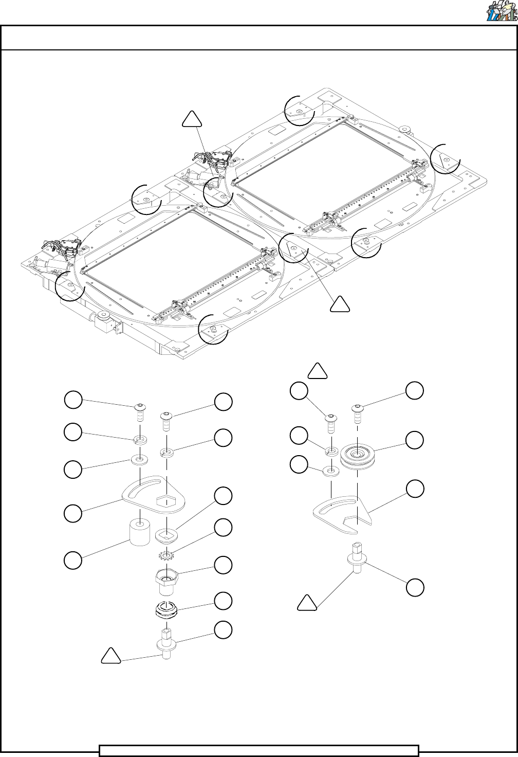
Page 10 TECHNICAL PUBLICATIONS T46230809 Rev . C Dual Rotary Positioning Assembly - BHS This Document Supports Assembly 46230809 113 (4) 74 (4) 128 (4) 130 (4) 132 (4) (4) 95 (4) 74 (4) 73 (4) 93 (4) 94 (4) 74 (4) 73 53 …
Page 9
TECHNICAL PUBLICATIONS
Dual Rotary Positioning Assembly - BHS T46230809 Rev.C
This Document Supports Assembly 46230809
(2)
(2)
29
30
150
151
12
125
24 (4)
17 (4)
58 (4)
139
26
(4)
155 (2)
126
(2)
17 (4)
24 (4)
15 (2)
149
3
(2) 110
123
122
81
80
156 (2)
(4) 73
(4) 74
Detail D
Detail E
Page 10
TECHNICAL PUBLICATIONS
T46230809 Rev. C Dual Rotary Positioning Assembly - BHS
This Document Supports Assembly 46230809
113 (4)
74 (4)
128 (4)
130 (4)
132 (4)
(4) 95
(4) 74
(4) 73
(4) 93
(4) 94
(4) 74
(4) 73
53 (4)
54 (4)
55 (4)
52 (4)
(4) 49
11
14
14
14
11
127 (4)
131 (4)
G
G
G
G
F
F
F
F
Detail F Detail G
Page 11
TECHNICAL PUBLICATIONS
Dual Rotary Positioning Assembly - BHS T46230809 Rev.C
This Document Supports Assembly 46230809
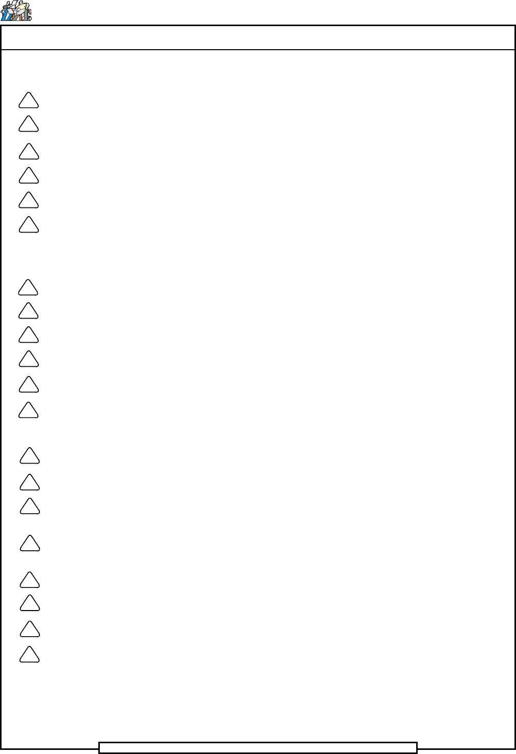
Drawing Notes:
Lubricate screws and torque to 90 IN-LB.
Bottom plunger and loosen 1/4 turn.
Apply Loctite 222 - UIC #BLKM07389.
Remove existing screws and replace with Det. 140 (2).
Remove stop block and dowel pins when board widths exceed 10.25 IN.
Used only with board widths up to 10.25 IN. Any board widths larger, remove guides and
use Det. 62 as a board guide. Remove Det. 140 and replace with screws located onbad
board hopper bracket. When not using Details 63 and 67, attach to bad board hopper
bracket.
Limit actuators to be set for 18 X 18 insertion area.
Assemble bearings face to face, see Detail H.
Replace existing set screws with Det. 78 (4).
Remove existing set screw and replace with Det. 34.
Apply Loctite 242 - UIC #BLKM07402.
Fasten with Loctite 495.
Secure Det. 49 (2) using the tapped hole that lies completely on pad.
Set up dimension from the face of the bearing bracket to the face of the pulley hub.
Locate the pulley on the shaft with the set screw, detail 34, then tighten the two #8 cap
head screws to secure the pulley to the shaft.
Orient the extended hub of the bearing to the right when viewing the shaft from the front of
the machine.
Do not wrap cable around encoder body.
With the leadscrew shaft through bearing bore, use 47492401 to torque to 65 ± 5 in-lbs.
Torque to 50 ± 5 in-lbs.
Leave a slight gap (up to 1/16 inch) between the shoulder on detail 1 and the inner face of
detail 44.
1
2
3
4
5
6
7
8
9
10
11
12
14
15
16
17
18
19
20
21