46230809.pdf - 第37页
Page 37 TECHNICAL PUBLICATIONS Dual Rotary Positioning Assembly - BHS T46230809 Rev .C This Document Supports Assembly 46230809 Bearing Removal Procedure 1. Power down the machine as detailed in the Operation Manual and …
Page 36
TECHNICAL P UBLICATIONS
T46230809 Rev. C Dual Rotary Positioning Assembly - BHS
This Document Supports Assembly 46230809
Advanced Support Information
The following corrective maintenance procedures are intended for
Universal Instruments Corporation Field Service Engineers only.
Unauthorized implementation of these procedures may result in damage
to the machine and may adversely affect your warranty status if
performed by other than UIC personnel.
The advanced support information procedures are those identified on the
maintenance concept table as requiring a minimum skill level of UIC Field
Service Engineer. All such procedures may or may not be present in this
document at this time.
Y Axis Bearing Replacement Procedure
Purpose:
This procedure is presented because of the need to properly seat the duplex
bearing for the Y axis lead screw support.
The Y axis lead screw support bearing is installed at the factory and
should not require removal. If a bearing should fail and need
replacement, the following procedure should be performed by a
qualified Field Service Engineer using the proper tools.
Special Tools:
Torque Wrench (47145501)
Bearing Assembly Tool (47492101)
Spanner Wrench (47492401)
Special Wrench (46860901)
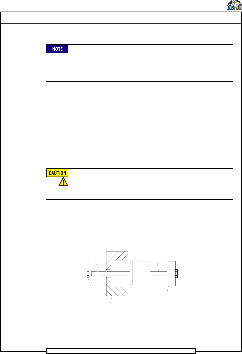
BEARING ASSEMBLY TOOL
Outer Race Support
(47513801)
Pilot
(47513601)
Puller Support
(47513701)
Bolt
(47513901
Nut
(80015003)
Washer
(80018809)
Page 37
TECHNICAL PUBLICATIONS
Dual Rotary Positioning Assembly - BHS T46230809 Rev.C
This Document Supports Assembly 46230809
Bearing Removal Procedure
1. Power down the machine as detailed in the Operation Manual and open
the rear cover of the machine.
2. Loosen the screws that secure the rear stiffener plate from the C-frame,
then remove the rear stiffener plate.
3. Loosen the two set screws in the flex coupling that secures the flex
coupling to the lead screw shaft
4. Remove the four screws, lockwashers and washers that secure the en-
coder and mounting plate assembly to the C-frame, then remove the
encoder and mounting plate assembly.
5. Loosen the four screws that secure the motor and mounting plate as-
sembly to the C-frame to relieve the tension on the drive belt. Slide the
drive belt off the pulley.
6. While holding the pulley to prevent it from turning, loosen the lock nut
and remove the lock nut and washer.
7. Loosen the set screws that secure the pulley to the lead screw shaft,
then remove the pulley, key and spacer.
8. Remove the screws that secure the dust bellow and retainer plate to the
bearing retainer and move the dust bellow out of the way.
9. Loosen the set screw that secures the bearing plug in the bearing plate,
then using the spanner tool, remove the bearing plug and plug washer.
10. Remove the two flat head screws that secure the bearing retainer and
bearing washer to the C-frame, then remove the bearing retainer and
bearing washer.
11. Remove the button head screw that secures the Y frame cover, then re-
move the Y frame cover.
12. Remove the three socket head screws that secure the bearing block at
the front of the lead screw, then remove the bearing block.
13. Move the positioning assembly toward the front of the machine until
the lead screw shaft is pulled out of the bearing.
If the lead screw turns while the positioning assembly is being moved
forward, the shaft may be stuck and require light impact to loosen it and
allow it to be pulled from the bearing.
14. Remove the duplex bearing from the C-frame, being sure not to dam-
age the bore in the C-frame. The bearing assembly tool may be used to
remove the duplex bearing.
Page 38
TECHNICAL P UBLICATIONS
T46230809 Rev. C Dual Rotary Positioning Assembly - BHS
This Document Supports Assembly 46230809
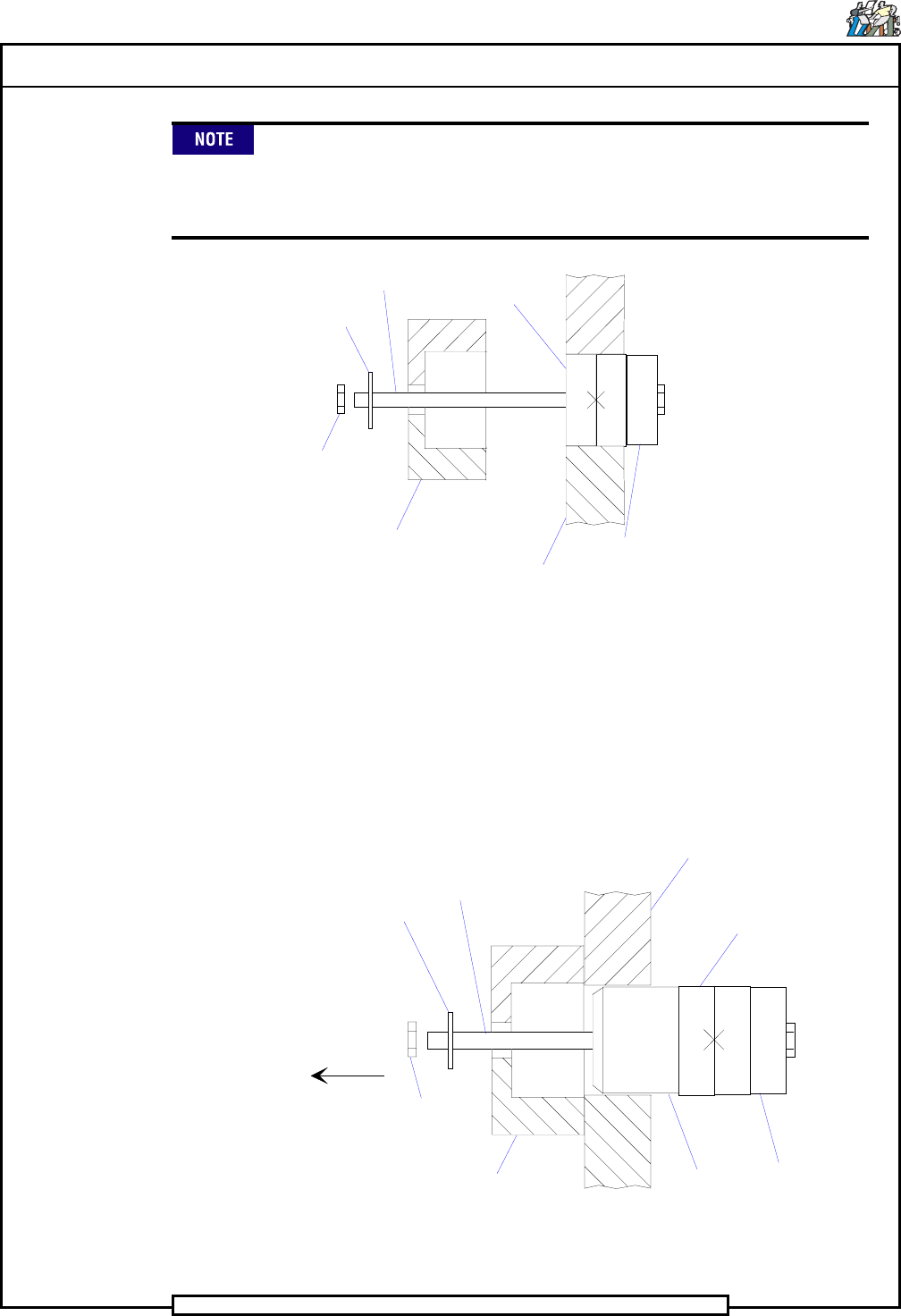
The bearing assembly tool may be used without the pilot to remove the
bearing from the C-frame. By engaging the tool, as shown below, turn
the nut on the bolt against the puller support until the bearing is
removed from the C-frame.
C-frame
Puller
Support
Duplex
Bearing
Outer Race
Support
Bolt
Nut
Washer
Bearing Installation Procedure
1. Slide the outer race support and duplex bearing onto the bolt then
thread the pilot against the duplex bearing as shown below. Ensure
that the markings (><) on the duplex bearing are aligned and facing
each other.
2. Place the pilot into the bore of the C-frame with the threaded end of the
bolt pointing towards the rear of the machine.
C-frame
Duplex
Bearing
Pilot
Outer Race
Support
Bolt
Nut
Puller
Support
REAR OF
MACHINE
Washer