46230809.pdf - 第24页
Page 24 TECHNICAL PUBLICATIONS T46230809 Rev . C Dual Rotary Positioning Assembly - BHS This Document Supports Assembly 46230809 X-Y Axes Encoder Adjustments Purpose: This procedure ensures that the positioning of the X-…
Page 23
TECHNICAL PUBLICATIONS
Dual Rotary Positioning Assembly - BHS T46230809 Rev.C
This Document Supports Assembly 46230809
Adjustment Procedure
Procedure:
1. Ensure the belt is correctly seated into both pulleys by rotating the pul-
leys several rotations. This can be accomplished by moving the appro-
priate axis by hand.
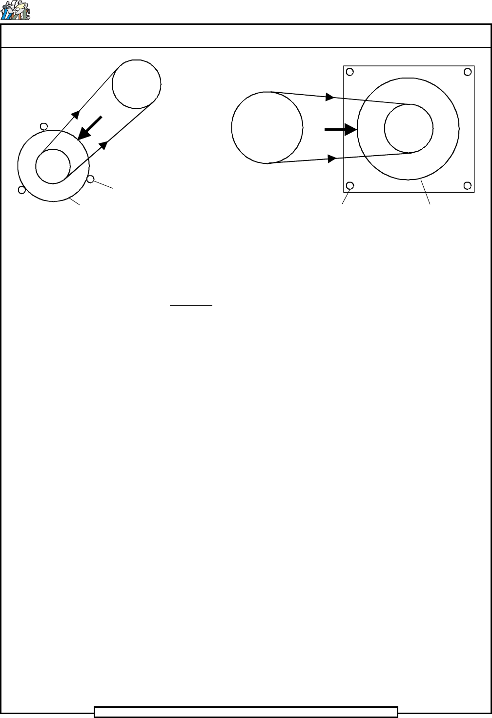
2. Loosen the motor mounting screws and allow the spring mechanism in
the mounting plate to apply a force against the side of the motor. The
force is applied in the direction shown, away from the lead screw pul-
ley and along the line between the centers of the pulleys.
3. With the force applied, again ensure the belt is correctly seated into
both pulleys by rotating the pulleys several rotations. This can be ac-
complished by moving the appropriate axis by hand.
4. While the spring mechanism maintains the required force against the
side of the motor, tighten the motor mounting screws .
End of procedure.
X-Axis Motor Y-Axis Motor
Motor
Motor Mounting Screws
Motor
Motor Mounting Screws
F
F
T
T
T
T
Page 24
TECHNICAL PUBLICATIONS
T46230809 Rev. C Dual Rotary Positioning Assembly - BHS
This Document Supports Assembly 46230809
X-Y Axes Encoder Adjustments
Purpose:
This procedure ensures that the positioning of the X-Y axis encoder settings
correspond with the position of head 1.
If any of the rotary encoders are misaligned, the head 1 position does not cor-
respond to the pattern program values.
Prerequisite Adjustment:
Rotary Disk Alignment
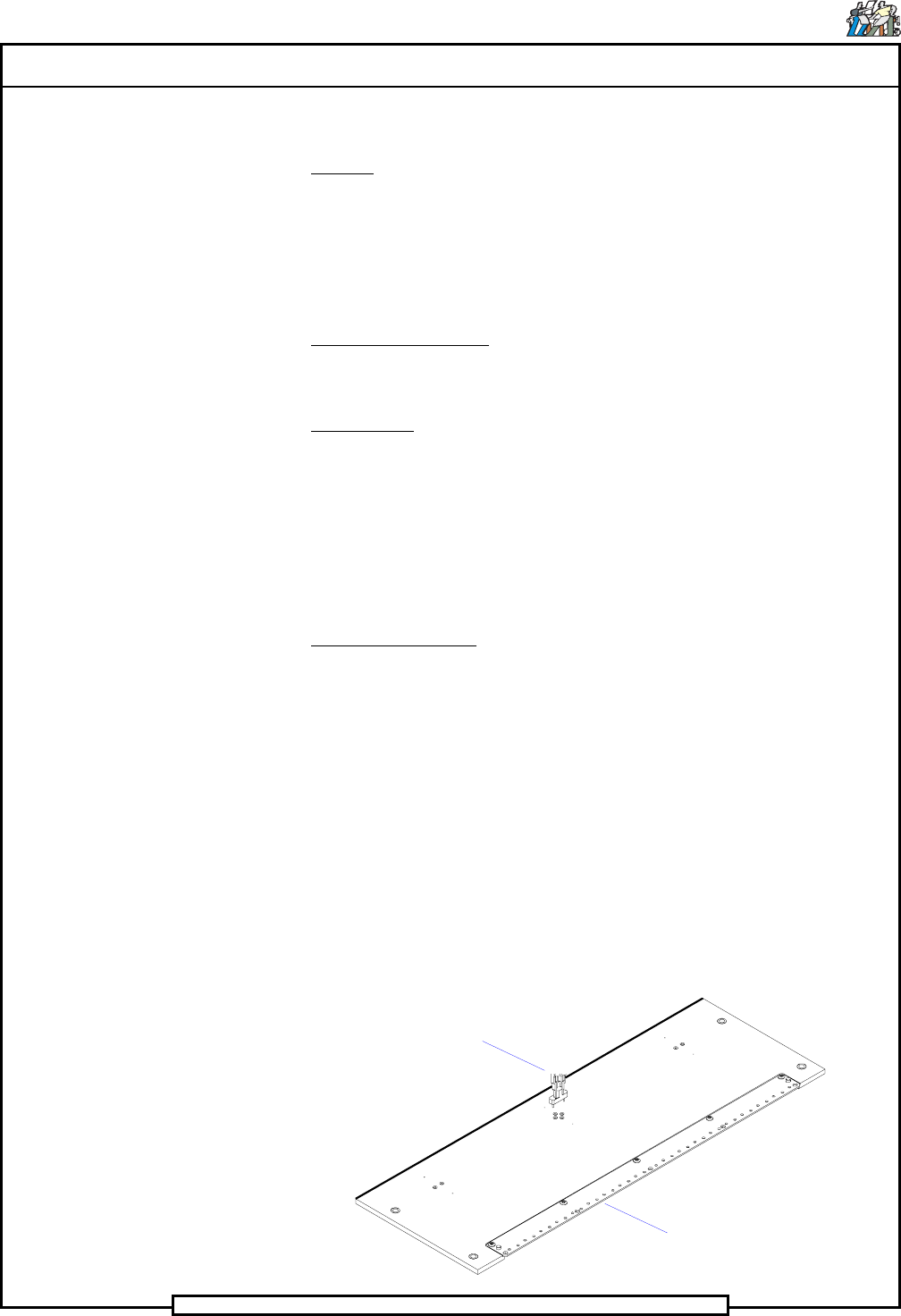
Special Tools:
Set Up Template (46367805)
Set up tool
(43806307 for jumper wire and large lead tooling)
(43806311 for standard, 5mm and 5.5mm tooling)
(43806312 for 5mm s/l tooling)
Span Adjustment head (47088701)
Head Drive Shaft (47084401)
Adjustment Procedure:
1. Push the STOP button.
2. Palm the machine down as detailed in the Operation Manual, then set
the limit switch actuators to the following set up dimensions.
X-axis: 3/4 inch from the end of the X-frame casting to the end of
the limit switch actuator.
Y-axis: 1/4 inch from the end of the sheetmetal actuator mounting
surface to the edge of the limit switch actuator block.
3. Using the head drive shaft tool, manually position the head tooling on
both insertion heads to the tool safe position to prevent possible dam-
age to the insertion tooling during positioning system movements.
Set Up Tool
Set Up Template
Page 25
TECHNICAL PUBLICATIONS
Dual Rotary Positioning Assembly - BHS T46230809 Rev.C
This Document Supports Assembly 46230809
4. Place the set up template on the rotary table beneath head 1 and secure
it in position using the locator pins and thumb screws.
5. Activate the IM Diagnostics as follows. Refer to the IM-UPS and IM
Diagnostics documentation for specific details relating to the operation
of the machine terminal.
Select the IM Diagnostics icon.
When the machine is in the IM Diagnostics function, power is provided
to the machine. Exercise caution when performing the following
procedures to avoid Injury to personnel and equipment.
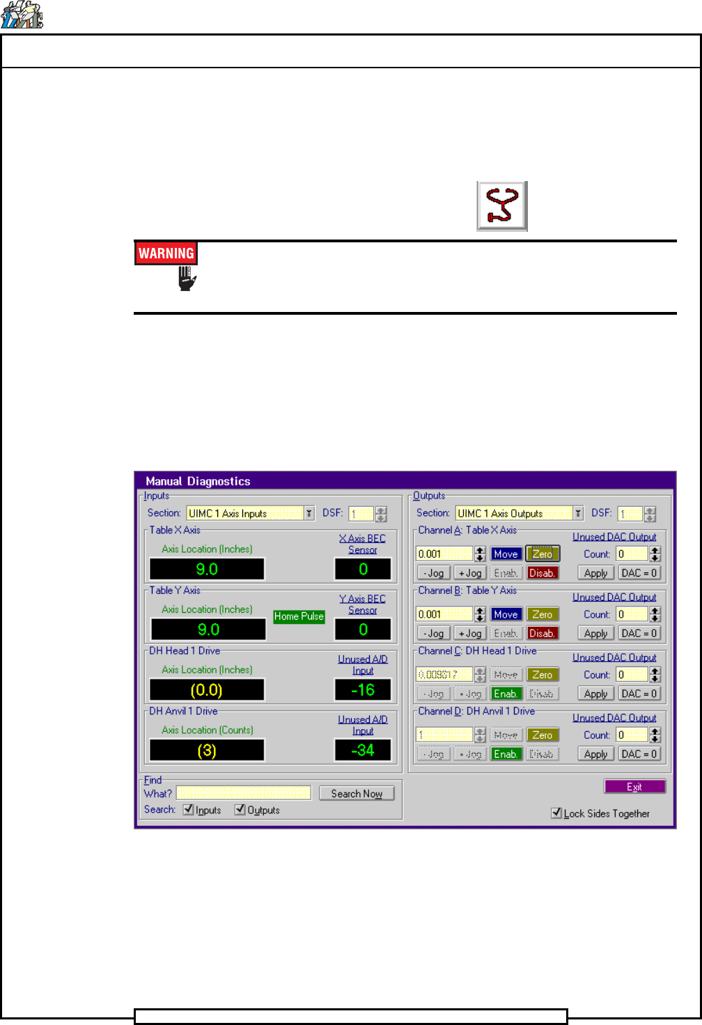
6. After the IM Diagnostics has completed its initialization, select the fol-
lowing. Diagnostics>Manual Diagnostics
The Manual Diagnostics screen is displayed
7. In the Outputs side of the Manual Diagnostics screen, select the follow-
ing. Section>UIMC 1 Axis Outputs
8. Palm the machine up and push the INTLK RESET push button.
9. Select Channel B: Table Y Axis>Zero
The Zero - Table Y Axis dialog screen is displayed.