46230809.pdf - 第28页
Page 28 TECHNICAL PUBLICATIONS T46230809 Rev . C Dual Rotary Positioning Assembly - BHS This Document Supports Assembly 46230809 17. Insert the set up tool into the outside formers. The tooling should be set so the tool …
Page 27
TECHNICAL PUBLICATIONS
Dual Rotary Positioning Assembly - BHS T46230809 Rev.C
This Document Supports Assembly 46230809
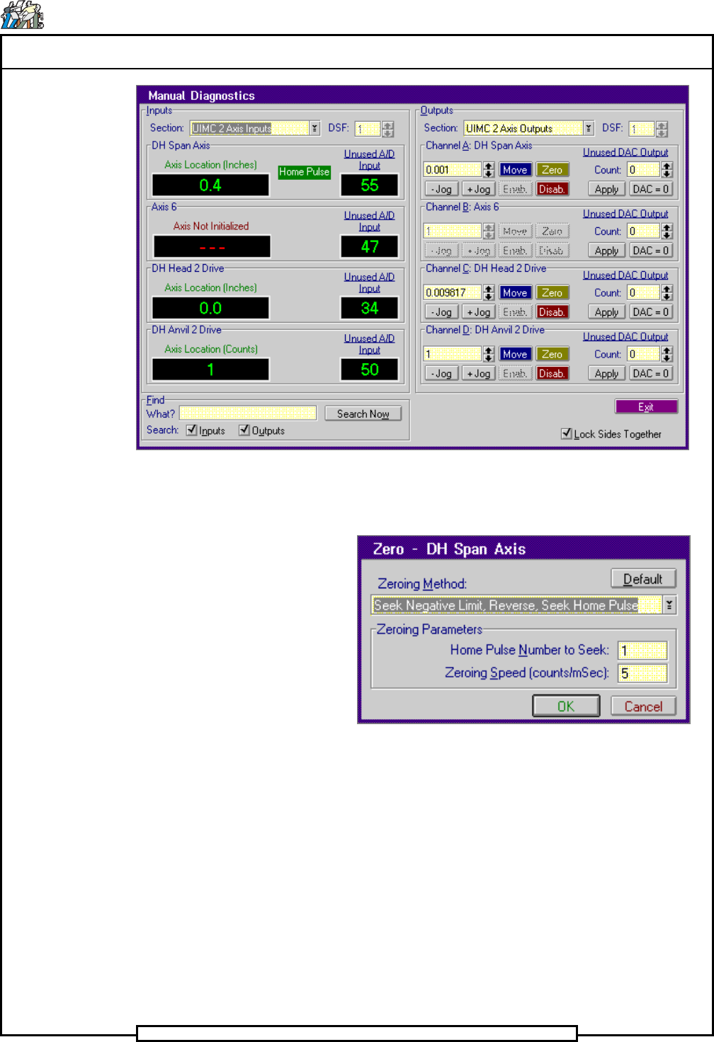
14. Select Channel A: DH Span Axis>Zero
The Zero - DH Span Axis dialog screen is displayed.
15. In the Zero - DH Span Axis dialog screen select Default then OK
The Manual Diagnostics screen is displayed.
- In the Channel A: DH Span Axis increment box, click on the up
or down ¯ arrows until 0.1 appears in the increment box.
- Click on the + Jog button until the Axis Location for the Table
Y Axis indicator in the Input side of the screen reads 0.4.
16. Set the X and Y axis circuit breakers, 2CB and 3CB, to the off position.
Page 28
TECHNICAL PUBLICATIONS
T46230809 Rev. C Dual Rotary Positioning Assembly - BHS
This Document Supports Assembly 46230809
17. Insert the set up tool into the outside formers.
The tooling should be set so the tool can be removed from the formers
and inserted back into the formers and held in position. If the tool does
not fit, perform the Span axis mechanical adjustment.
18. Using the head service wrench, manually lower the insertion head so
the set up tool is just above the set up template.
The center of the set up tool should be no more than 0.5 inches
(12,7mm) away from the holes in the template. If it is more than 0.5
inches, remove the set up tool, adjust the negative limit switch actuator
and return to step 7.
19. In the increment box for both the X and Y axis select 0.001 inch incre-
ments and jog the axes until the set up tool extends into the holes in the
template without deflecting the pins or stricking the template.
20. Click on the Disab. button for both the X and Y axes.
21. For each axis, the Axis Location should read 9.0 inches. If either read-
ing is not correct, loosen the appropriate encoder securing hardware
and rotate the encoder until the respective Axis Location display
reads 9.0 inches and the Home Pulse display appears. Tighten the
encoder securing hardware.
22. Manually raise the insertion head to the tool safe position and remove
the set up tool from the outside formers.
23. Repeat step 7 through 12 to zero and position the X and Y axes.
24. Install the set up tool in the outside formers then check the adjustment
by manually lowering the insertion head until the set up tool extends
into the holes in the template.
Ensure set up tool pins do not flex or bend the template as they enter
the holes.
25. Manually raise the insertion tooling then remove the set up tool from
the outside formers and the set up template from the rotary table.
26. Set the X and Y axis circuit breakers, 2CB and 3CB, to the on position.
27. Exit out of the IM Diagnostics function.
End of procedure.
Page 29
TECHNICAL PUBLICATIONS
Dual Rotary Positioning Assembly - BHS T46230809 Rev.C
This Document Supports Assembly 46230809
X-Y Axes Limit Switch Adjustments
Purpose:
When activated, the X and Y limit switches prevent the tables from being
driven into their mechanical limits. The Y limit switches and X limits
switches are all made by separate actuators.
Prerequisites:
X and Y Axes Encoder Adjustments
Adjustment Procedures:
1. Push the STOP button.
2. Palm the machine down as detailed in the Operation Manual.
3. Using the head drive shaft tool, manually position the head tooling on
both insertion heads to the tool safe position to prevent possible dam-
age to the insertion tooling during positioning system movements.
4. Activate the IM Diagnostics as follows. Refer to the IM-UPS and IM
Diagnostics documentation for specific details relating to the operation
of the machine terminal.
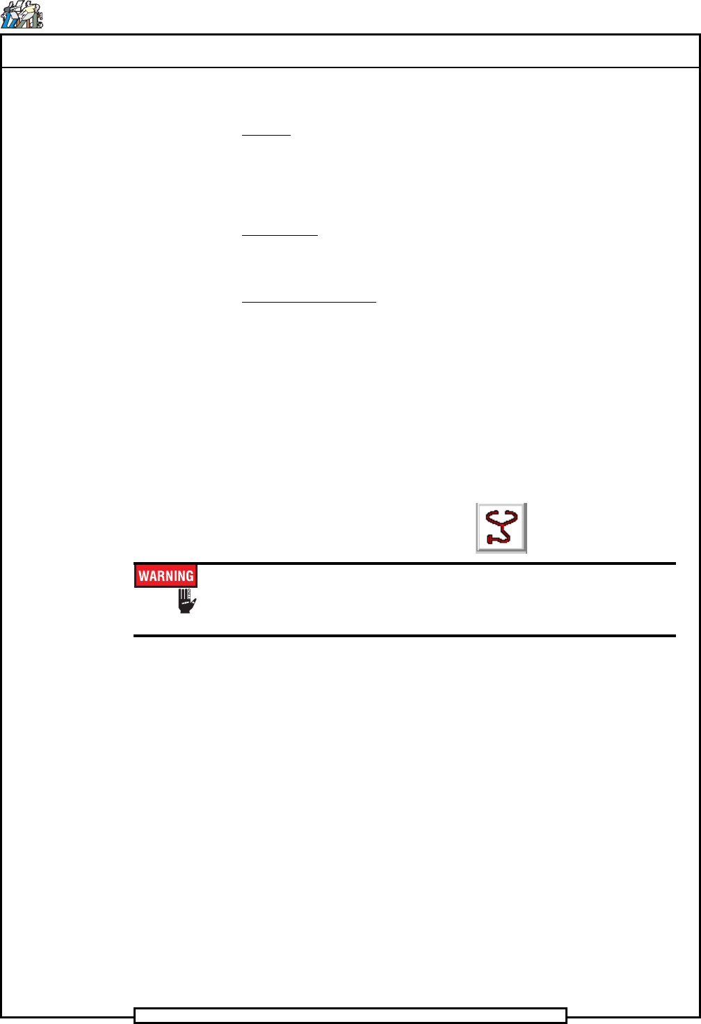
Select the IM Diagnostics icon.
When the machine is in the IM Diagnostics function, power is provided
to the machine. Exercise caution when performing the following
procedures to avoid Injury to personnel and equipment.
5. After the IM Diagnostics has completed its initialization, select the fol-
lowing. Diagnostics>Manual Diagnostics
The Manual Diagnostics screen is displayed
6. In the Outputs side of the Manual Diagnostics screen, select the follow-
ing. Section>UIMC 1 Axis Outputs
7. Palm the machine up and push the INTLK RESET push button.