46230809.pdf - 第34页
Page 34 TECHNICAL P UBLICATIONS T46230809 Rev . C Dual Rotary Positioning Assembly - BHS This Document Supports Assembly 46230809 Rotary Disk Slow Down Adjustments Purpose: This adjustment ensures that the rotary disk de…
Page 33
TECHNICAL PUBLICATIONS
Dual Rotary Positioning Assembly - BHS T46230809 Rev.C
This Document Supports Assembly 46230809
Do not move the negative limit actuator excessively. Excessive
movement will disrupt the zero position of the axis and may require axis
encoder adjustment.
End of procedure.
Y Axis Positive Limit
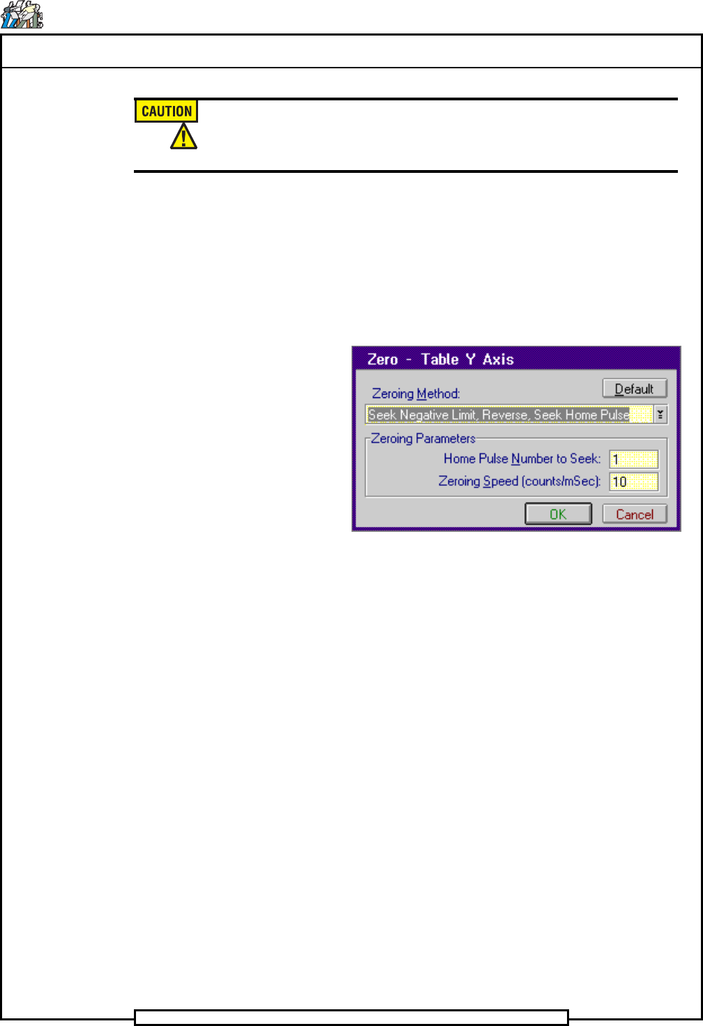
1. Select Channel B: Table Y Axis>Zero
The Zero - Table Y Axis dialog screen is displayed.
2. In the Zero - Table Y Axis dialog screen select Default then OK
The Manual Diagnostics screen is displayed.
- In the Channel B: Table Y Axis increment box, click on the up
or down ¯ arrows until 1.0 appears in the increment box.
3. Click on the + Jog button until the Axis Location display reads 18.0
inches.
4. In the Channel B: Table Y Axis increment box, click on the up or
down ¯ arrows until 0.010 appears in the increment box.
5. Click on the + Jog button until one of the following occurs.
a. The position of the Y-axis in the Axis Location display is
between 18.080 and 18.150. In this case, move the limit switch
block until the positive limit just actuates, then secure the
actuator. Zero the axis and jog to the limit to verify the correct
limit position.
b. A positive hard limit occurs, the Hard Limit indicator is
displayed. In this case, move the actuator block away from the
limit switch then repeat steps 1 through 5.
End of procedure

Page 34
TECHNICAL P UBLICATIONS
T46230809 Rev. C Dual Rotary Positioning Assembly - BHS
This Document Supports Assembly 46230809
Rotary Disk Slow Down Adjustments
Purpose:
This adjustment ensures that the rotary disk decelerates before contacting the
lock assembly and fully engages the lock assembly without excessive force.
The rotary disk slow down switch assembly is actuated by the stop blocks on
the rotary disk. When a stop block contacts the ball actuator on the slow
down assembly, air flow to the drive assembly is reduced slowing the speed
of the rotary tables.
Correct rotary disk slow down assembly adjustment increases reliability and
longevity of the lock assembly.
Adjustment Procedure:
1. Loosen the screws securing the slow down sensor mounting bracket.
2. Adjust the slow down assembly sensor mounting bracket as far away
from the lock assembly as possible. Ensure the ball actuator is in line
with a stop block.
3. Adjust the ball actuator so the stop blocks on the rotary table fully actu-
ate the ball but do not deflect the slow down assembly or the mounting
bracket.
4. Manually rotate the rotary table so the stop blocks actuate the slow
down sensor, while adjusting the front/back position of the sensor.
5. Tighten the hex head screws to secure the slow down sensor bracket in
position.
6. Adjust the slow down needle valve clockwise until it is closed.
7. Adjust the drive motor flow control valve counterclockwise until it is
open.
8. Create a dummy rotary disk drive pattern, refer to the IM-UPS Refer-
ence Manual. The pattern must include four index steps with 9.0 x 9.0
inch (2286,0 x 2286,0 mm) X and Y values, a bypassed insertion step
and a bypassed park step.
9. Load and activate the rotary disk drive pattern.
10. In the IM-UPS Machine Status window, select the following. Display
Status>Operation Status
The Operations Mode screen is displayed.
11. In the Head On box, deselect the Head 1 and Head 2 check boxes..
12. Push the START push button to zero the machine.
Page 35
TECHNICAL PUBLICATIONS
Dual Rotary Positioning Assembly - BHS T46230809 Rev.C
This Document Supports Assembly 46230809
13. Push the START push button again to activate the rotary tables.
14. As the rotary table indexes, slowly turn the needle valve (NV1 or
NV1A) to achieve a condition in which the rotary disk stop block
firmly enters the lock assembly without causing a banging sound.
15. Push the STOP push button to stop the rotary table indexing.
16. Loosen the lock screw on the air flow control valve on the drive assem-
bly.
17. Adjust the air flow control valve fully clockwise and then two full turns
counterclockwise.
18. As the disk rotates, adjust the flow control valve so the disk movement
is quick but the stop blocks do not strike the lock assembly with exces-
sive force. The rotary disc should rotate ninety degrees in approxi-
mately one second with both discs set at the same speed.
It may be necessary to adjust the pneumatic slow down needle valve to
achieve this adjustment.
19. Tighten the lock screw on the flow control valve to secure the valve in
position.
20. Push the STOP push button.
End of procedure.