00197787-02_SI_SIPLACE_HeadVerification_EN.pdf - 第72页
6 Description of the test results 6.19 Segment offset up & down (fast) 72 Software Manual SIPLACE Head Verification 03/2018 6.19 Segment offset up & down (fast) 6.19.1 Measurement principle Segment offset up &…

6 Description of the test results
6.18 Nozzle spring
Software Manual SIPLACE Head Verification 03/2018 71
6.18.3 Interpretation of the results obtained
‘Nozzle spring’ / ‘Signal threshold’ error for all segments
Cause Solution
Light barrier Z-down defective ► Check the Z-axis down light barrier and re-
place it if necessary.
‘Nozzle spring’ / ‘Signal threshold’ error for individual segments
Cause Solution
Segment spring is bent or mechanically dam-
aged.
► Replace the DP.
The position, fixture or state of the cover switch-
ing ring is faulty.
► Check the fixture and, if necessary, re-
place the cover switching ring.
Spring pin at back of DP lock damaged. ► Replace the head.

6 Description of the test results
6.19 Segment offset up & down (fast)
72 Software Manual SIPLACE Head Verification 03/2018
6.19 Segment offset up & down (fast)
6.19.1 Measurement principle
Segment offset up & down (fast) is a quick measurement to determine the eccentricity of a seg-
ment to the center of the component camera.
●
Segment offset up is the offset of the segment center in the up position to the center of the
component camera.
●
Segment offset down is the offset of the segment center in the bottom position to the center
of the component camera, either for the pick-up or placement of components. It is also known
as the offset between the PCB camera center and the center of the component camera.
During the measurement, the PCB camera measures the initial position of the calibration tool (CT)
in the calibration tool pocket. The CT is picked up by each segment which is turned to 0° and
moved to the component camera, where the CT is measured (optically centered) again. The de-
termined offset values are then used to calculate the CT position. Afterwards, the CT is placed
back into the calibration tool pocket where it is measured another time by the PCB camera. The de-
termined offset values are then used to calculate the CT position.
NOTICE
Termination of test sequence
If a measurement shows a segment outside the allowed limits, all subsequent measure-
ments will be terminated. It is assumed that the segment is seriously deformed and that the
head is no longer able to perform.
► Replace the segment immediately before performing other measurements.
6 Description of the test results
6.19 Segment offset up & down (fast)
Software Manual SIPLACE Head Verification 03/2018 73
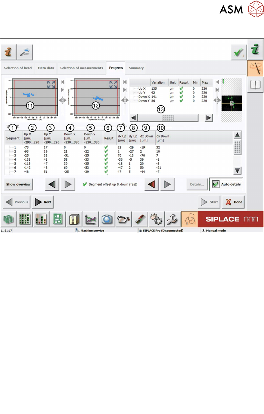
6.19.2 Measurement result
Fig.53: Result view – Segment offset up and down (fast)
1 Measured Segment
2 Calculated Segmentoffsetup value "UpX":
UpX
Segment (1)
is used as the reference to calculate the other segment offsets.
UpX
Segment (n)
= UpX
Segment (1)
+ dxUp
Segment (n)
– dxUp
Segment (1)
3 Calculated Segmentoffsetup value "UpY":
The calculation follows the same principle as for UpX.
4 Calculated Segmentoffsetdown value "DownX":
DownX
Segment (1)
= 0 and is used as the reference to calculate the other segment offsets:
DownX
Segment (n)
= dxDown
Segment (n)
– dxDown
Segment (1)
5 Calculated Segmentoffsetdown value "DownY":
The calculation follows the same principle as for DownX.
6 Result view indicating if the values are within (green tick) or outside (red cross) the limits.
7 Measured Segmentoffsetup value “dxUp”.
8 Measured Segmentoffsetup value “dyUp”.
9 Measured Segmentoffsetdown value “dxDown”.
10 Measured Segmentoffsetdown value “dyDown”.
11 Graph showing the calculated Segmentoffsetup values "Up X" and "Up Y".
12 Graph showing the calculated Segmentoffsetdown values "DownX" and "DownY".