00197787-02_SI_SIPLACE_HeadVerification_EN.pdf - 第83页
6 Description of the test results 6.23 Z-Axis travel distance Software Manual SIPLACE Head Verification 03/2018 83 6.23 Z-Axis travel distance 6.23.1 Measurement principle The Z-axis travel distance measurement determine…

6 Description of the test results
6.22 Z-axis movement
82 Software Manual SIPLACE Head Verification 03/2018
6.22.3 Interpretation of the results obtained
‘End position Z’ error for all segments
Cause Solution
Z-axis linear guide defective ► Replace the complete Z-axis unit.
‘End position Z’ error for individual segments
Cause Solution
If all three measured values are outside of the
limits, the linear guide of the segment is defect-
ive.
► CPP: Replace the linear guide of the seg-
ment.
► C&P20P/A: Replace the DP station.
One of the three measured values being outside
of the limits indicates an increasing stiffness of
the segment.
► CPP: Prepare the linear guide for the seg-
ment to be replaced.
► C&P20P/A: Prepare the DP station to be
replaced.
6 Description of the test results
6.23 Z-Axis travel distance
Software Manual SIPLACE Head Verification 03/2018 83
6.23 Z-Axis travel distance
6.23.1 Measurement principle
The Z-axis travel distance measurement determines the maximum travel range and indicates the
condition of the Z-axis drive and linear guide.
●
The Z-axis is moved up and down several times until it reaches the limit. For each movement,
the position is determined at which the axis stopped. If the Z-axis moves easily to the limit, the
Z-axis drive and linear guide are in good condition.
●
If the current sensor is triggered and the Z-axis is not moving smoothly, a mechanical problem
exists.
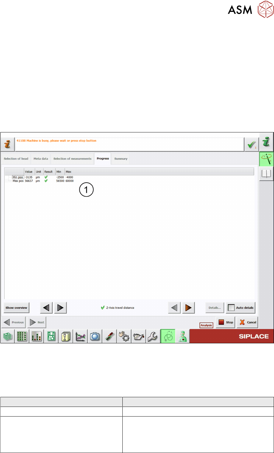
6.23.2 Measurement result
Fig.57: Result view – Z-axis travel distance
1 Minimum and maximum position determined when moving the Z-axis.
6.23.3 Interpretation of the results obtained
‘Z-axis travel distance’ error
Cause Solution
Blockage at the Z-axis linear bearing ► Check / maintain the linear bearing.
Z-axis drive and/or linear bearing defective ► Check / maintain the linear bearing.
► Replace the P&P module.
► Send the P&P module to ASM for customer spe-
cific repair.
6 Description of the test results
6.24 ZDS sensor values
84 Software Manual SIPLACE Head Verification 03/2018
6.24 ZDS sensor values
6.24.1 Measurement principle
The ZDS sensor values measurement determines the functionality of the Z-down light barrier and
the component sensor, in accordance with the rotary angles of the DP or segment.
Firstly, the reference run is applied to determine the brightness adjustment for the Z-down light bar-
rier (LED Gain). In relation to this, the voltage value is determined for the Z-down light barrier,
which provides a reference value (sensor value [mV]) for the distance to the switching ring.
Additional measurements are performed to determine the Z-down light barrier voltage values when
the switching ring issues the Z axis end position signal during placement (spring resp. low [mV])
and also when the Z axis makes contact at full force (spring resp. high [mV]), corresponding to a
complete compression of the segment spring.
In further tests, the rotary axis of the DP / segment is rotated by a full rotation (360°) while the Z-
down light barrier voltage values are constantly recorded and an image of the distance from the Z-
down light barrier to the switching ring is recorded as well. The changes in voltage are measured in
steps of 5°, to prove a relatively even fluctuation. The entire change in voltage is also determined
over the complete 360°.
As this measurement is performed in the component sensor area, the changes in nozzle tip length
can be measured across the entire 360°. These changes in length are recorded in steps of 5° and
must remain within a certain range.
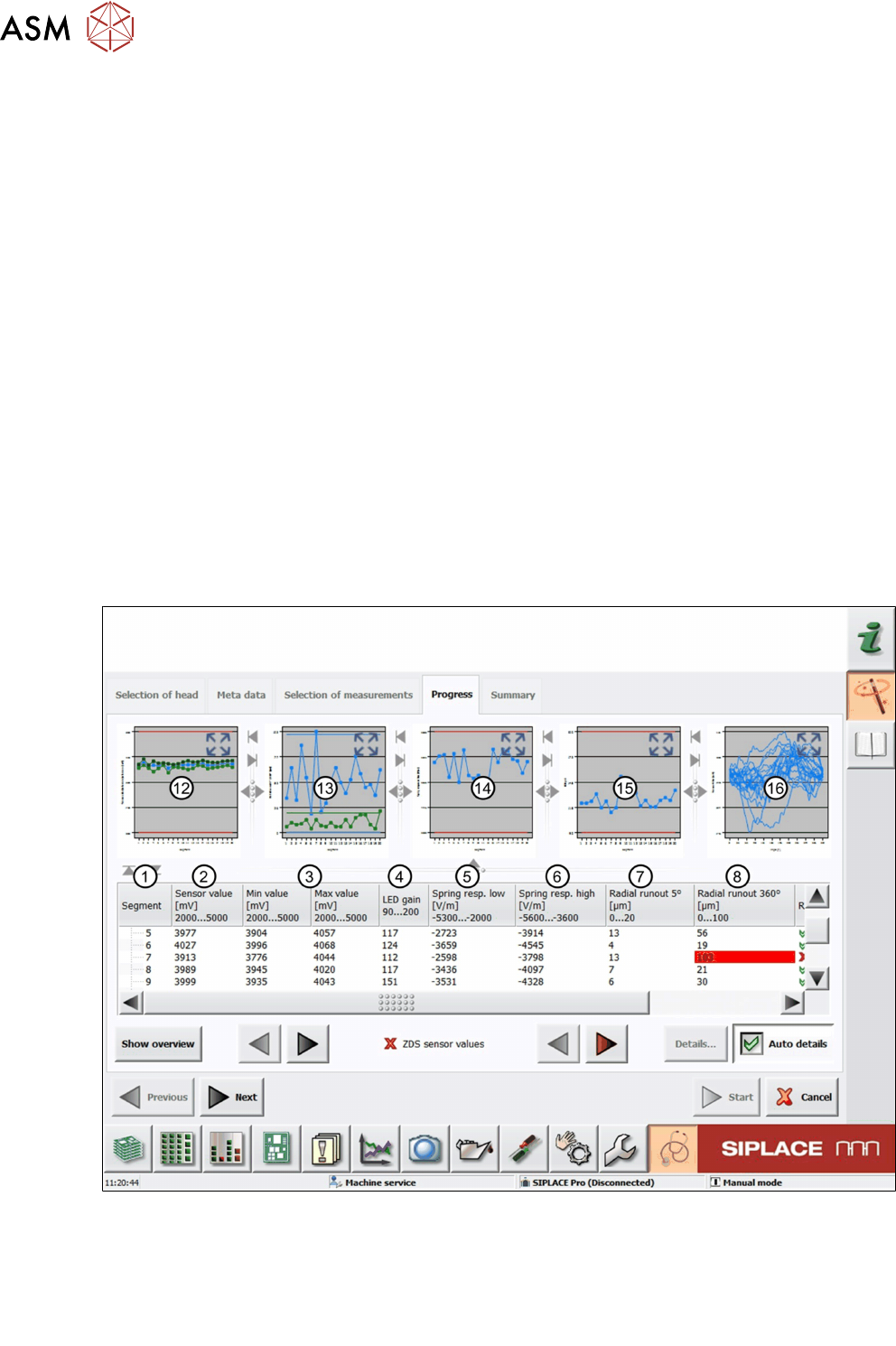
6.24.2 Measurement result
Fig.58: Result view – ZDS sensor values 1/2
1 Measured Segment
2 The Sensorvalue is the mean value of the Minvalue and Maxvalue measurement.
3 Values of the Minvalue and Maxvalue measurement.
4 Value of the LEDgain measurement.