222085 Issue 1 - Horizon APiX Appendix Manual.pdf - 第66页
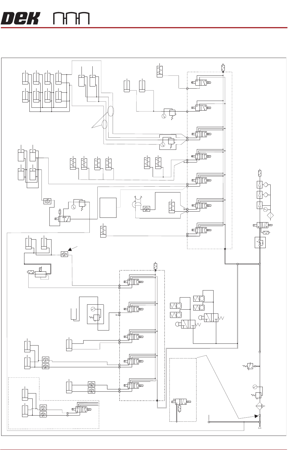
TECHNICAL REFERENCE APPENDIX PNEUMATIC SCHEMATICS Chapter Issue 1 June 15 Appendix to Micron Technical Manuals 3.29 PNEUMA TIC SCHEMA TICS Figure 3-5 Pneumatic Sc hematic Sheet 1 T o Grid-Lok T ooling See Board Support T…
TECHNICAL REFERENCE APPENDIX
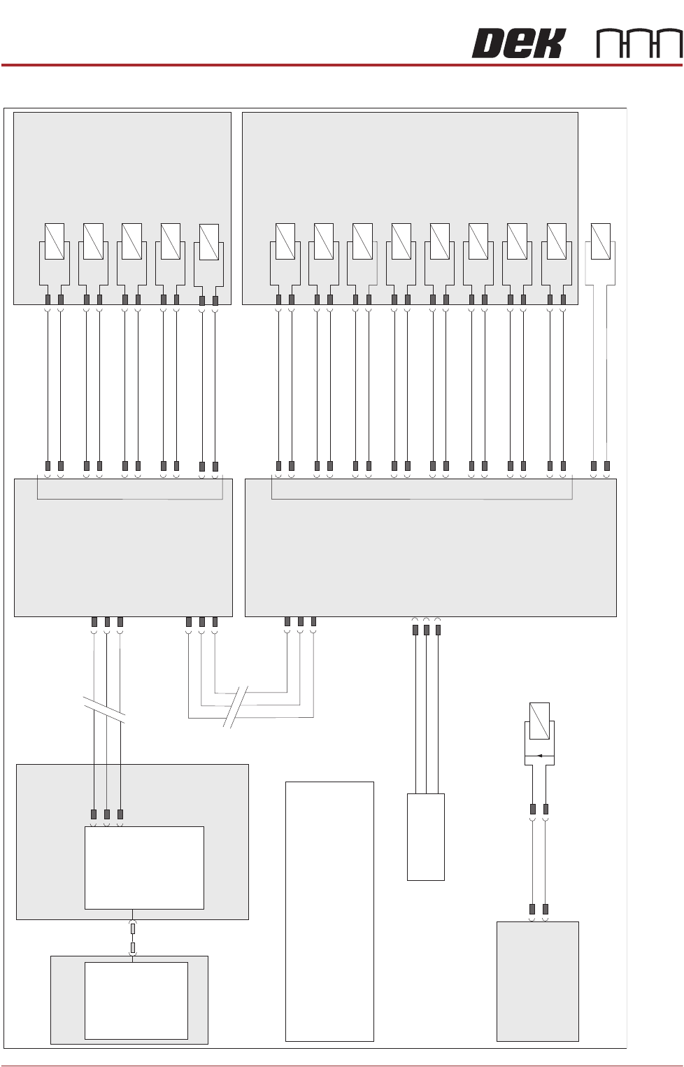
ELECTRICAL SCHEMATIC
3.28 Appendix to Micron Technical Manuals Chapter Issue 1 June 15
ELECTRICAL SCHEMATIC
M36 Machine
Control Enclosure
Main Machine
I/O Node 2
N2PL7
1
2
3
DIG IN 0
Air Pressure SW
8SE11
+12V
Sig
0V
PC
USB
Motherboard
NextMove ES
(I/O Node 1)
1
2
4
CAN_H
CAN_L
CAN GND
M36PL35
CAN Bus
N3SK2
7
2
3
CAN In
N2SK2
7
2
3
CAN Out
N3SK3
7
2
3
Print Carriage
I/O Node 3
N3SK8
N2SK4
N2SK2
9SK28
Auto Drip Tray
9SOL28
DIG OUT 6
0V
4
12
9SK27
Paste Disp. Tilt
9SOL27
DIG OUT 5
0V
3
11
16SK22
Rail Board Stop
16SOL22
DIG OUT 12
0V
6
16
9SK26
Paste Disp.
9SOL26
DIG OUT 4
0V
2
10
9SK25
ProFlow Paste
9SOL25
DIG OUT 3
0V
1
9
16SK14
Board Stop/RTC
Rail Width Clamp
16SOL14
DIG OUT 10
0V
4
16
16SK10
Board Clamps
16SOL10
DIG OUT 9
0V
9
16
9SK29
Screen Load
9SOL29
DIG OUT 7
0V
5
13
16SK07
Screen Clamps
16SOL07
DIG OUT 8
0V
2
15
16SK31
Chase Clamps
16SOL31B
DIG OUT 7
0V
1
14
16SK08
USC Squeegee
16SOL08
DIG OUT 14
0V
9
21
16SK31
16SK03
Lid Bolt
16SOL31A
Inroad Vane Lift
(RTC Machine)
16SOL03
Venturi Vac Unit
8SOL24
DIG OUT 11
DIG OUT 0
DIG OUT 15
0V
0V
0V
5
1
22
14
2
23
Machine Rear Solenoids
Print Carriage Solenoids
NOTE
The breaks in the CAN Bus chain reflect that
additional I/O Nodes may be fitted, refer to
Machine Control chapter for the complete
CAN Bus chain.
M39 Emergency
Machine Off
Enclosure
1
2
M3 PL94
16SK37
+ve
-ve
Pneumatic
Dump Valve
16SOL37
TECHNICAL REFERENCE APPENDIX
PNEUMATIC SCHEMATICS
Chapter Issue 1 June 15 Appendix to Micron Technical Manuals 3.29
PNEUMATIC SCHEMATICS
Figure 3-5 Pneumatic Schematic Sheet 1
To Grid-Lok Tooling
See Board Support
Tooling Chapter
Pneumatic Dump
Valve. Only fitted
to machines
with M39 EMO.
5/2
9SOL29
5/2
9SOL28
5/2
9SOL27
5/2
9SOL25
Screen Load
Actuator
A
B
ASM Rail Lock
Rail Clamps
Left
Rail Clamps
Right
Out
Paste Dispense
In
Reg/Assy
IN
P
Out
R
Vacuum
Tooling
Venturi Vacuum Tooling (optional)
Pressure
Sense
Filter/Reg Assy
Mains
Air In
At 4.5 Bar
Minimum
3/2 Dual
16SOL31A
5/2
16SOL08
5/2
16SOL07
5/2
16SOL03
5/2
16SOL10
5/2
16SOL14
A
B
A
B
A
B
A
B
A
B
A
Lid Bolt
RTC Vane Clamp
Lift Sol/
Heavy Palete Rails
Snugger
ProFlow ATx Only
3/2 Dual
16SOL31B
B
5/2
9SOL26
A
B
Chase Clamps
Only one
connection
depending on type
'C' Chase/ASM
Screen Clamps
Standard - 8 Clamps
Machined C Chase - 4 Clamps
ASM Screen Clamps
Screen Clean
Squeegee Bar
(optional)
Proclean
Screen Clean
Squeegee Bar
(optional)
Board Clamps
Grid-Lok
Control
Unit
Machine Rear Solenoids
A
B
A
B
A
B
Print Carriage Solenoids
Auto Drip Tray
Paste Dispense
Tilt
ProFlow + SCAR
(optional)
5/2
9SOL28/29
A
B
Semi Auto Screen Load/
Screen Load Actuator
Board Clamp
Reg (optional)
In Out
Camera
Board Stop
Remote Board
Stop
TECHNICAL REFERENCE APPENDIX
CALIBRATIONS
3.30 Appendix to Micron Technical Manuals Chapter Issue 1 June 15
CALIBRATIONS
Squeegee Module
Squeegee Pressure
Calibration
Squeegee pressure calibration is carried out on machines after the following
circumstances:
• The squeegee mechanism is replaced
• The strain gauge bridge in the squeegee mechanism is replaced
• The rising table sensors have been replaced or adjusted
A force meter calibration jig and squeegee pressure plate are required to
perform the squeegee pressure calibration.
NOTE
1. Ensure that the rising table print reference height is set correctly before
commencing, (the calibration relies upon accurate positioning of the table to
make a reference).
2. Ensure that the Pressure Hardware parameter in Maintenance\Machine
Setup\Options is set to FITTED.
Use the following procedure to calibrate the squeegee pressure:
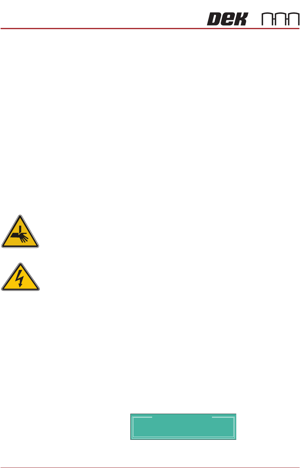
WARNING
BOARD CLAMPS. EXTREME CARE MUST BE EXERCISED WHEN WORKING IN
THE TOOLING AREA OF THE MACHINE TO AVOID INJURY. THE FOILS ON THE
FRONT AND REAR BOARD CLAMPS ARE VERY SHARP.
1. From the Ready page, select Unload Screen.
2. Open the front printhead cover.
3. Remove the screen from the machine.
4. Remove the tooling (if fitted) from the manual tooling plate.
5. Close the front printhead cover.
6. Press the System button.
7. Select Maintenance.
8. Select Calibrations.
9. Select Pressure.
10. Select Calibrate Readings.
The rails are checked for the presence of a board, the print carriage moves
to the calibration position, the rear rail moves to home position, the table
homes and the board clamps are closed.
11. The machine cover is unlocked and the message ‘Fit the pressure calibra-
tion rig’ is displayed with the following window:
12. Open the front printhead cover.
13. Ensure that the calibration jig is secured to the mounting plate as shown in
SEMI 2
CALIBRATION DATA
Gain Factor
1.02