222085 Issue 1 - Horizon APiX Appendix Manual.pdf - 第73页
TECHNICAL REFERENCE APPENDIX CALIBRATIONS 3.36 Appendix to Micron Technical Manuals Chapter Issue 1 June 15 33. Use Next or Previous to hig hlight Camera Axes . 34. Select Select Module . 35. Use Next or Previous to hig …

TECHNICAL REFERENCE APPENDIX
CALIBRATIONS
Chapter Issue 1 June 15 Appendix to Micron Technical Manuals 3.35
Camera System Module
Board Stop X Offset Check
WARNING
BOARD CLAMPS. EXTREME CARE MUST BE EXERCISED WHEN WORKING IN
THE TOOLING AREA OF THE MACHINE TO AVOID INJURY. THE FOILS ON THE
FRONT AND REAR BOARD CLAMPS ARE VERY SHARP.
1. Select Open Cover Commands.
2. Select Carriage To Rear.
3. Select Unload Screen.
4. Open the front printhead cover.
5. Remove the screen.
6. Close the front printhead cover.
7. Press the System button.
8. Select Back.
9. Select Maintenance.
10. Select Diagnostics.
11. Use Next or Previous to highlight Camera Axes.
12. Select Select Module.
13. Use Next or Previous to highlight Home Camera X Axis.
14. Select Run Diagnost.
15. Use Next or Previous to highlight Home Camera Y Axis.
16. Select Run Diagnost.
17. Use Next or Previous to highlight Drive to Board Stop Position.
18. Select Run Diagnost.
19. Select Exit.
20. Use Next or Previous to highlight Rail System.
21. Select Select Module.
22. Use Next or Previous to highlight Toggle Board Stop.
23. Select Run Diagnost.
24. Open the front printhead cover.
25. Place a board onto the rails and move it up against the board stop.
26. Close the front printhead cover.
27. Press the System button.
28. Use Next or Previous to highlight Toggle Board Clamp.
29. Select Run Diagnost.
30. Use Next or Previous
to highlight Toggle Board Stop.
31. Select Run Diagnost.
32. Select Exit.
SEMI 2
TECHNICAL REFERENCE APPENDIX
CALIBRATIONS
3.36 Appendix to Micron Technical Manuals Chapter Issue 1 June 15
33. Use Next or Previous to highlight Camera Axes.
34. Select Select Module.
35. Use Next or Previous to highlight Initialise Vision System.
36. Select Run Diagnost.
37. Select Exit.
38. Open the front printhead cover.
39. Place a non-magnetic rule flat against the board edge and slide a second
rule so that it abuts it and comes within the camera field of view.
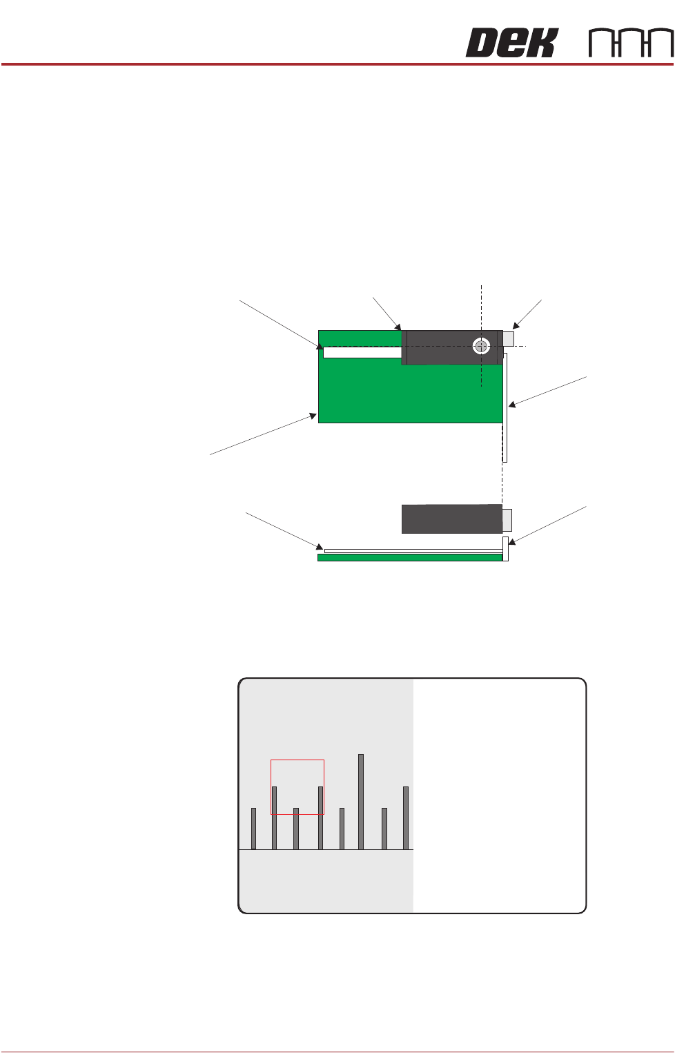
40. On the vision monitor, record the distance from the board edge to the
approximate centre of the square (figure below refers). This value is the
Board Stop X Offset and should be -43.5mm ±0.5mm.
Camera
Camera Board Stop
Metric Rule
Metric Rule
Board
Metric Rule
Side View
Metric Rule
Plan View
45
43 4644

TECHNICAL REFERENCE APPENDIX
CALIBRATIONS
Chapter Issue 1 June 15 Appendix to Micron Technical Manuals 3.37
NOTE
The numerals on the rule may not be directly in the field of view, move the
rule until the numerals are visible in the vision window. Lay the rule flat on
the board, do not lift or angle it as this can distort the measurement. As the
board stop is before the camera the distance is recorded as a minus reading.
41. Remove the rule from the machine.
42. Close the front printhead cover.
43. Press the System button.
44. Select Exit.
45. During Initialisation, remove the board from the transport rails when
prompted.
46. Select Continue.
47. Select Back.
48. Select Maintenance.
49. Select Machine Setup.
50. Select Basics.
51. Select Board Stop X Offset.
52. Enter the dimension obtained in Step 40.
53. Select Accept.
54. Select Back.
55. Select Back.
56. Select Back.
Vision System
Calibration
For the vision alignment to function accurately a full system calibration is
required. This should be carried out by the maintenance personnel at the
required period.
The calibration of the vision system is carried out in two stages using a
calibration screen (Part No. 134764) and a calibration board (Part No. 134765).
The first stage, Calibrate Vision, details the calibration of X, Y and Theta.
Calibrate Video X, Y calculates the screen movement in millimetres to vision
system pixels. This is achieved by looking up at the calibration screen fiducials
and moving the screen in the X and Y directions by a fixed amount, for each of
the 25 fiducials.
The movements are calculated for each fiducial and the mean taken. This
average screen movement is recorded and used as part of the calibration data.
Calibrate Theta calibrates the screen theta movement. The camera selects
three screen fiducials and the screen moves in theta (using the two X axes and
implementing +2mm in X rear and -2mm in X forward to achieve the theta
movement). The movements are calculated for each fiducial and the average
taken. The data is recorded and the calibration is complete.
The second stage, Calibrate Offset is to compensate for any optical discrepan-
cies of the telecentric camera between viewing up and down. This is achieved
by printing the calibration screen and measuring the differences between the
centroid of the screen fiducials and the centroid of the printed fiducials. The