222085 Issue 1 - Horizon APiX Appendix Manual.pdf - 第81页
TECHNICAL REFERENCE APPENDIX CALIBRATIONS 3.44 Appendix to Micron Technical Manuals Chapter Issue 1 June 15 10. Using a t achometer fitted with t he surface speed te st wheel, positioned on the input or output pulley of …
TECHNICAL REFERENCE APPENDIX
CALIBRATIONS
Chapter Issue 1 June 15 Appendix to Micron Technical Manuals 3.43
Transport Rails
NOTE
Where the printer is connected to inline equipment make sure that the FMI
functionality is turned OFF before proceeding.
The front and rear board transport belts are driven independently by two
variable speed motors. Inevitably one motor drives faster than the other motor.
It is necessary to calibrate these motors so that they drive at the same speed.
Feeder motor speed is measured using a tachometer on the input or output
pulley and adjusted by a potentiometer control on each motor.
Calibration
Procedure
1. Remove the right hand side safety cover to gain access to the transport belt
motors.
2. Select Maintenance.
3. Select Diagnostics.
4. Use Next or Previous to highlight Rail System.
5. Select Select Module.
6. Use Next or Previous to highlight Belt Speed Calibration.
7. Select Run Diagnost.
The following window is displayed:
NOTE
Belt Speed Calibration figures displayed on this page have no relevance to
the belt speeds on the machine.
8. Select Front L 2 R Speed.
9. Select Incr. or Decr. to start the belts
SEMI 2
Belt Speed Calibration
64
64
64
64
64
64
64
64
FRONT L 2 R SPEED
FRONTR 2 L SPEED
REAR R 2 L SPEED
REAR R 2 L SPEED
FRONT L 2 RALT SPEED
FRONTR 2 L ALT SPEED
REAR L 2 RALT SPEED
REAR R 2 L ALT SPEED
TECHNICAL REFERENCE APPENDIX
CALIBRATIONS
3.44 Appendix to Micron Technical Manuals Chapter Issue 1 June 15
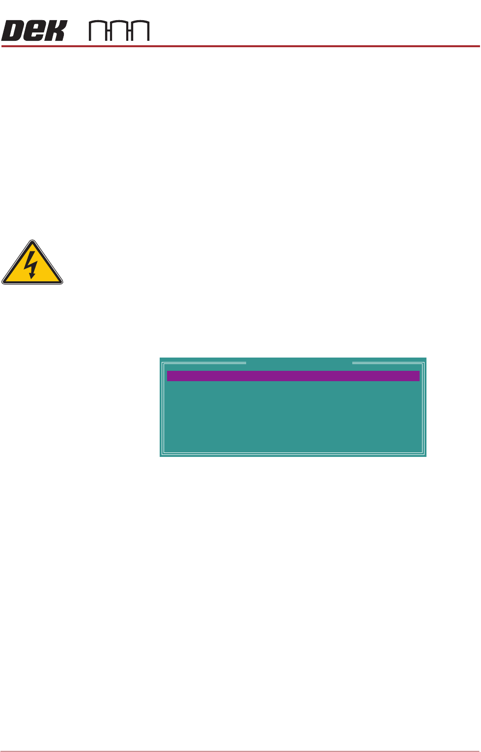
10. Using a tachometer fitted with the surface speed test wheel, positioned on
the input or output pulley of the front belt motor, measure the speed of the
motor right to left.
NOTE
For heavy board option the ‘Front’ settings refer to the rear rail and the ‘Rear’
settings refer to the front rail.
11. Ensure that one of the following speeds is achieved:
a. 29 to 31 m/min for standard transport rails.
b. 37 to 39 m/min for heavy board transport rails.
c. Repeat steps 10 and 11 a for Front R 2 L, Rear L 2 R, and Rear R 2 L.
12. In the table highlight Front L 2 R ALT Speed.
Rear Belt Speed using Digital Tachometer
Surface Speed Test Wheel
TECHNICAL REFERENCE APPENDIX
CALIBRATIONS
Chapter Issue 1 June 15 Appendix to Micron Technical Manuals 3.45
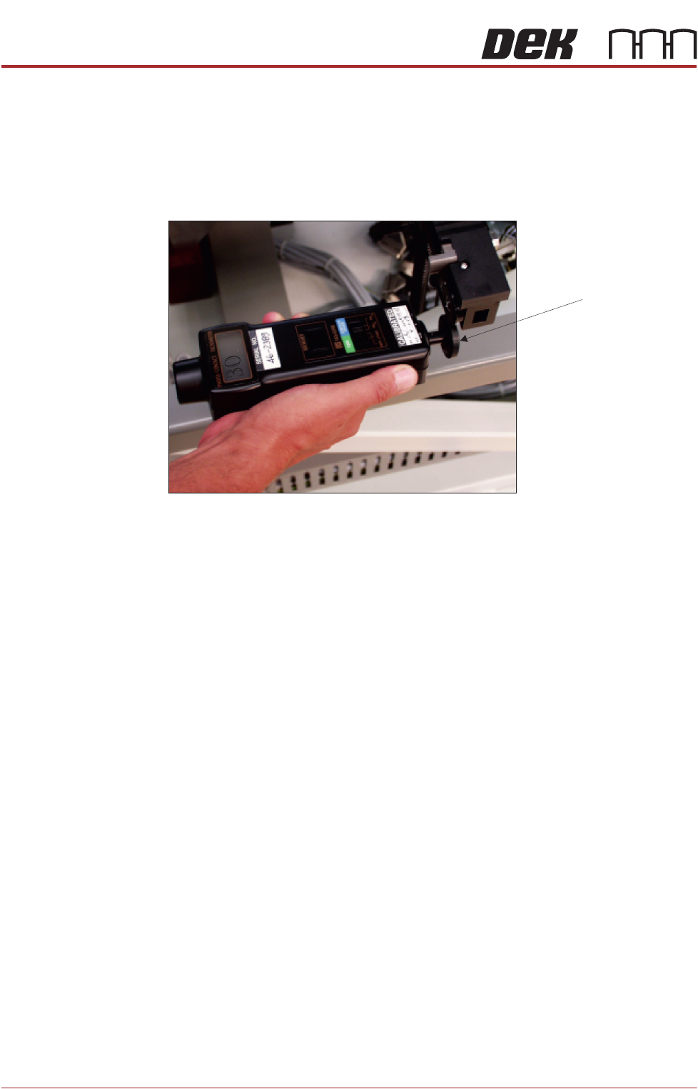
13. Using a tachometer fitted with the surface speed test wheel, positioned on
the input or output pulley of the front belt motor, measure the speed of the
motor right to left.
NOTE
For heavy board option the ‘Front’ settings refer to the rear rail and the ‘Rear’
settings refer to the front rail.
14. Select Incr. or Decr. to adjust the motor speed to achieve 14 to 16 m/min.
15. Repeat steps 13 and 14 for Front R 2 L Alt Speed, Rear L 2 R Alt Speed,
and Rear R 2 L Alt Speed.
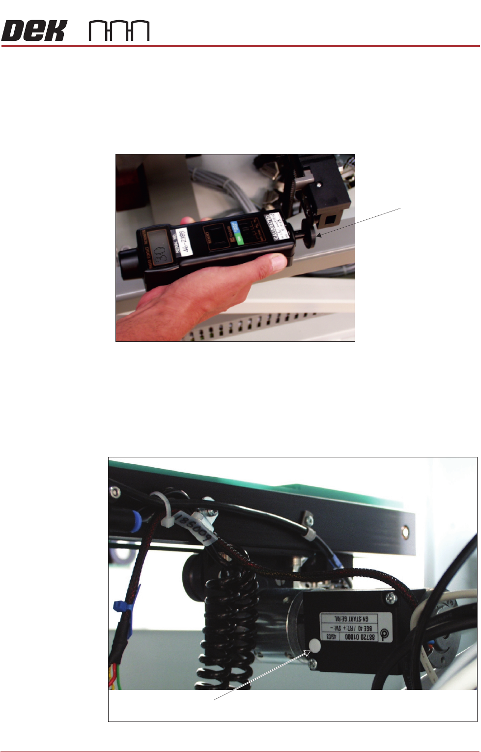
16. If adjustment is required, remove the belt speed adjuster cap on the appro-
priate motor and adjust using a suitable trimming tool.
17. Select Next.
Rear Belt Speed using Digital Tachometer
Surface Speed Test Wheel
Belt Speed Adjuster Cap
View on Front Rail Transport Belt Drive Motor