00197964-01_AI_Flex-Head-Options-Configuration_en.pdf - 第21页
Installing Flex Option 2 Assembly Instructions SIPLACE E 21 ► On the machine, remove the yellow covers shown. ► Connect the Tube Nozzle Changer LOC1 tube [03102149-xx] (diameter 6 mm) to port 3 (1) of the air service uni…
Installing Flex Option 2
20 Assembly Instructions SIPLACE E
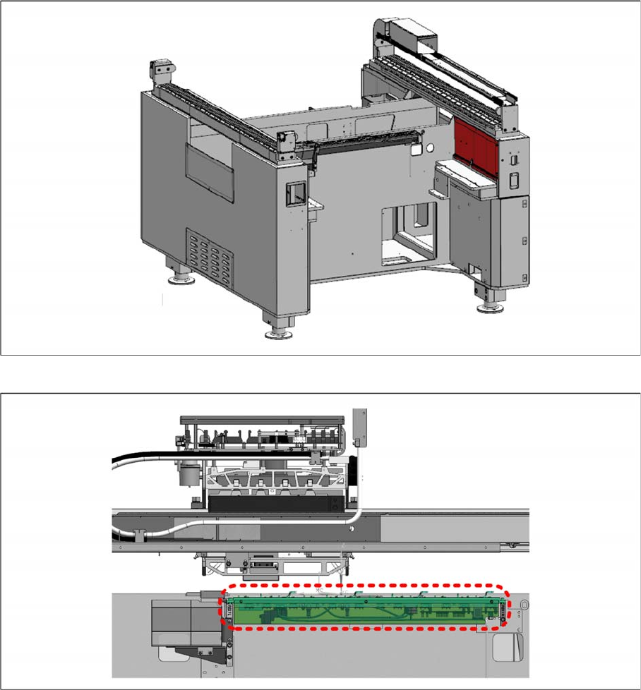
► Remove the red cover shown and locate the nozzle changer control cable [03102710-xx].
► Connect the cable [03102710-xx] to the cable of the nozzle changer NC single row [03106322
-
xx]
for SIPLACE CP6/CP12 (DLM 4), SIPLACE CP14 P.
► Mount the nozzle changer onto the shim covers on both ends and secure with four M5x14 cap
screws.
Installing Flex Option 2
Assembly Instructions SIPLACE E 21
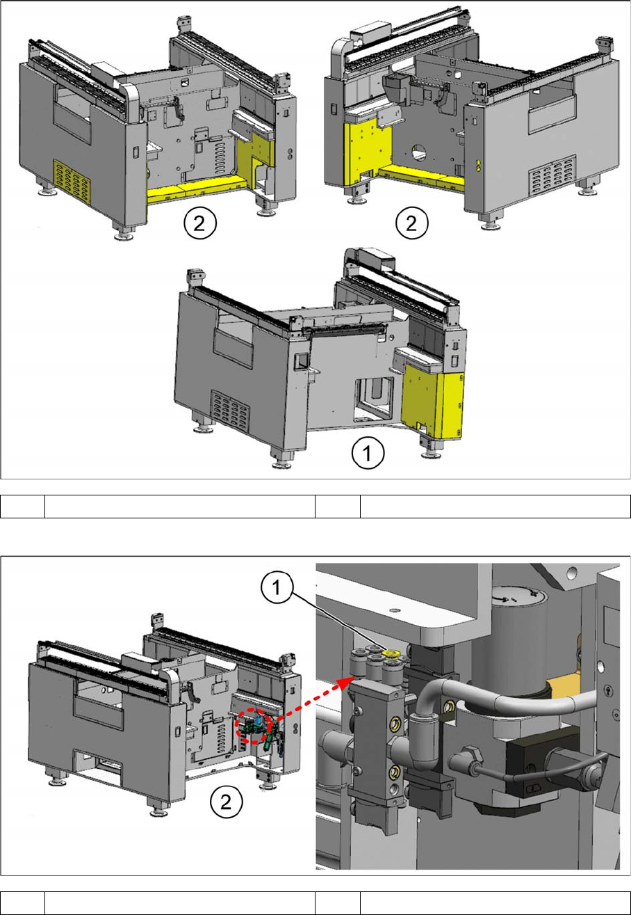
► On the machine, remove the yellow covers shown.
► Connect the Tube Nozzle Changer LOC1 tube [03102149-xx] (diameter 6 mm) to port 3 (1) of the air
service unit.
1 Location 1 2 Location 2
1 Port 3 2 Location 2
Installing Flex Option 2
22 Assembly Instructions SIPLACE E
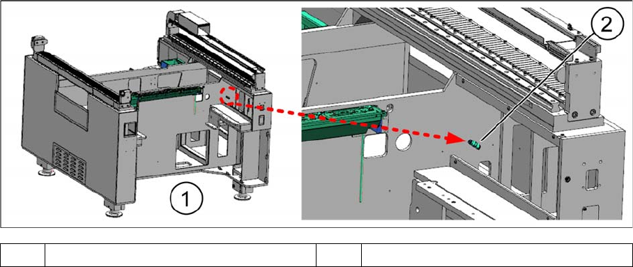
► Route the tube [03102149-xx] from the air service unit in location 2 to the indicated area in location 1.
► Connect the tube [03102149-xx] to the tube of the nozzle changer via the provided reducer fitting
QS-6-4 [00386293-xx] (2).
► Re-install the covers that you previously removed.
1 Location 1 2 Reducer fitting QS-6-4