YG12F_Ope_E.pdf - 第124页
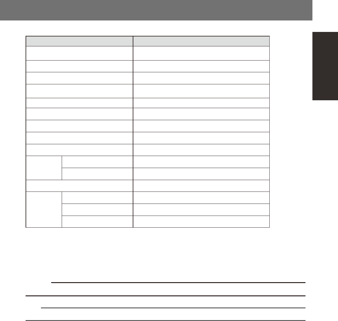
A-1 Appendix A1. Specifications n YG12F series specifications Item Specifications Operating ambient temperature Function guaranteed: 15 to 35°C Accuracy guaranteed: 20 to 28°C Operating ambient humidity 20 to 90% (no con…

A-1
Appendix
A1. Specifications
n
YG12F series specifications
Item Specifications
Operating ambient temperature
Function guaranteed: 15 to 35°C
Accuracy guaranteed: 20 to 28°C
Operating ambient humidity 20 to 90% (no condensation), optimal range: 50 to 60%
Noise level 78dB
Power requirement (voltage and frequency) 3-phase AC 200/208/220/240/380/400/416 V ± 10%, 50/60 Hz
Average power consumption 1.1kW
Power cable (conductor cross-section area) 3.5 mm
2
or more
Overvoltage category *
1
Category III
Pollution degree *
1
Degree 2
Supply air pressure *
2
0.60~0.70MPa
Air flow rate
YG12F 120Nl/min, Instantaneous maximum flow rate: 310Nl/min
YG12F+ATS15 130Nl/min, Instantaneous maximum flow rate: 320Nl/min
Board transport height *
3
900 mm ± 10 mm
Data
Number of mounting points *
4
10,000 points
Number of part types 255 types per board
Number of fiducial marks *
5
128 sets per board
*1: Conforms to IEC60664-1.
*2: Clean, dry air passed through an air dryer and filter.
*3: Distance from the floor surface to the upper surface of conveyor belt.
*4: Decreases with the number of boards, blocks and fiducial marks.
*5: When using 2-point fiducial mode.
c
Conveyor's board sensors may fail to detect a production board if it has a slit or cutout.
n
NOTE
For more detailed information not listed above, please refer to specification sheets.

S-1
Index
A
Alarm buzzer 1-2
ATS15 1-12
Axis configuration 1-16
Blow station 1-17
Board clamping method 2-23
Board production
Ending production 3-6
Pre-operation check 2-18
Resuming operation 3-4
Starting production 3-1
Starting the machine 2-19
C
Caution labels xv
CE marking i
Component supply section 1-11
Component trays 2-32
Connection between machines 1-2
Conveyor unit 1-15
Conveyor unit setup 2-23
Conveyor width 2-12
[Convey-out stop] button 3-6
[Cycle Stop] button 3-6
Data input unit 1-3
Dummy feeder iv
E
Emergency stop
Canceling emergency stop 2-1
Error
Clearing an error 2-2
Errors and troubleshooting 2-3
Feeder plates 1-11
Air connector 1-11
Power supply connector 1-11
Feeder setup section 1-11
Fixed 24-feeder plate 1-11
H
Head assembly 1-5
5-in-line multi-head assembly 1-6
K
Keyboard 1-3
Machine main unit 1-1
Names and functions of major parts 1-1
Manual feeder operation 2-15
Manual head operation 2-14
Manual I/O operation 2-16
[Monitor] button 3-8
Mouse 1-3
Multi-vision camera 1-6
N
Nozzle shaft blow 1-18
Nozzle station 1-9
Nozzle types 1-7
Narrow adjacent type 1-8
Standard type 1-7
One-stop cover iv
Operation panel 1-3
[READY] button 2-1
Operation panel buttons 1-4
[ACTIVE] button 1-4
[EMERGENCY STOP] button 1-4
[ERROR CLEAR] button 1-4
[READY] button 1-4
[RESET] button 1-4
[START] button 1-4
[STOP] button 1-4
Operation screen 2-8
Menu button area 2-8
Status area 2-8
Operation speed 3-3
[Operator] button 2-20
P
Pallet 1-13
Setting a pallet 2-33
Password 2-20
Pick Rate Warning 3-22
Pickup position offset 3-20
Power switch 1-2,2-19
Turning power off 3-6
Pressure gauge 1-2
Production monitors 3-8
Push-up pin 2-25
Q
QFP dump station 1-23
R
Recognition system 1-15
Return-to-origin 2-19
S
Safety ii
Safety cover 1-2
Safety message vi
Setup screen 2-11
[Check Nozzles] button 3-3
[Feed Bulk] button 3-3
[Required Nozzles] button 3-3
[Required Parts] button 3-2
Signal light 1-2
Specifications A-1
T
Tape feeder
Operation check 2-37
Settings on the mounter side 2-34
Setting the tape 2-26
Tray changer 1-12
Tray components 2-32
U
Unit screen 2-12
W
Warming up 2-21
[Warm Up] button 2-21
Warning labels x
"watch-and-wait" mode 3-24