YG12F_Ope_E.pdf - 第51页
1-17 1 Part names and functions 7. Other options 7.1 Blow station The blow station blows high-pressure air internally through the nozzles and shafts to blow away dust and grit and clean the nozzles. Blow station Blow sta…
1-16
1
Part names and functions
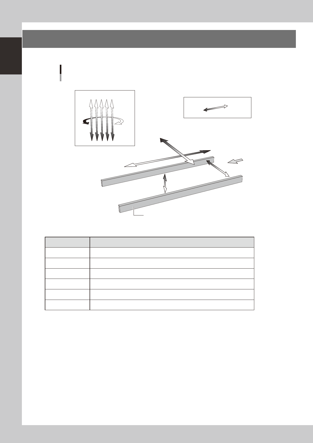
6. Axis configuration
The machine axis configuration and operation are shown in the drawing and table below.
Y axis
X axis
W axis
PU axis
Plus direction
Minus direction
Board
Conveyor rail
R axis
Head
Axis configuration
Z1Z2Z3Z4Z5
23115-M7-00
n
Function of each axis
Axis Function
X Moves the head assembly in parallel with the board flow on the conveyor.
Y Moves the head assembly perpendicular to the board flow on the conveyor.
Z1 to Z5 Controls the height of each head.
R Rotates the nozzle shafts of each head.
W Changes the conveyor width.
PU Moves the push-up plate vertically.
1-17
1
Part names and functions
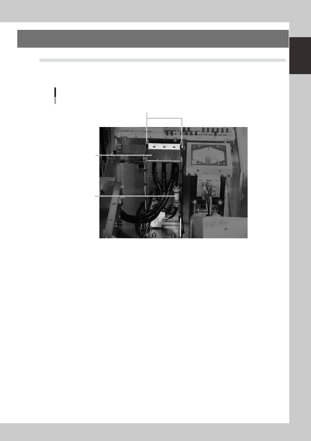
7. Other options
7.1 Blow station
The blow station blows high-pressure air internally through the nozzles and shafts to blow away dust and grit
and clean the nozzles.
Blow station
Blow station
3-hole type
Air filter
Sensor for detecting
nozzles left on blow station
23116-M7-00
1-18
1
Part names and functions
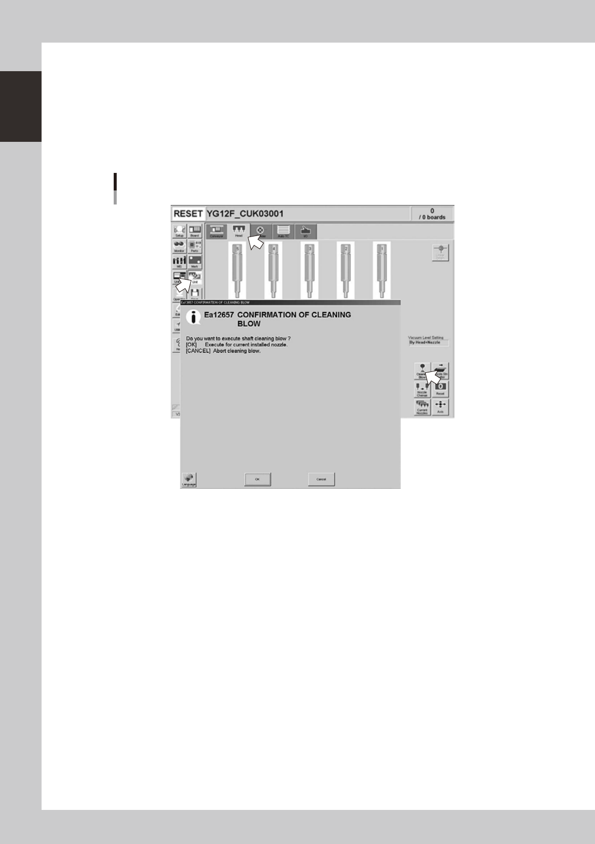
7.1.1 Performing a nozzle shaft blow
This section explains how to manually perform a nozzle shaft blow at any desired timing.
1
Open the [Unit] – [Head] tab screen.
2
Press the [Cleaning Blow] button.
A confirmation dialog box appears asking whether to perform nozzle shaft blow.
Press the [OK] button to perform nozzle shaft blow and proceed to the next step. If you want to cancel
nozzle shaft blow, press the [Cancel] button.
Nozzle shaft blow
24100-M7-00