YG12F_Ope_E.pdf - 第82页
2-24 2 asic operation 3.4.1 Conveyor unit setup flow Set up the convey units as sho wn in the flowc hart below . Adjust conveyor width Set board on conveyor Press [Width] button. Set push-up pins Board is clamped Raise…
2-23
2
asic operation
3.4 Adjusting the conveyor unit setup
When the board type to be produced is changed, the conveyor unit setup must be adjusted, and the feeders
prepared to match that board type. This section describes how to change the conveyor unit setup.
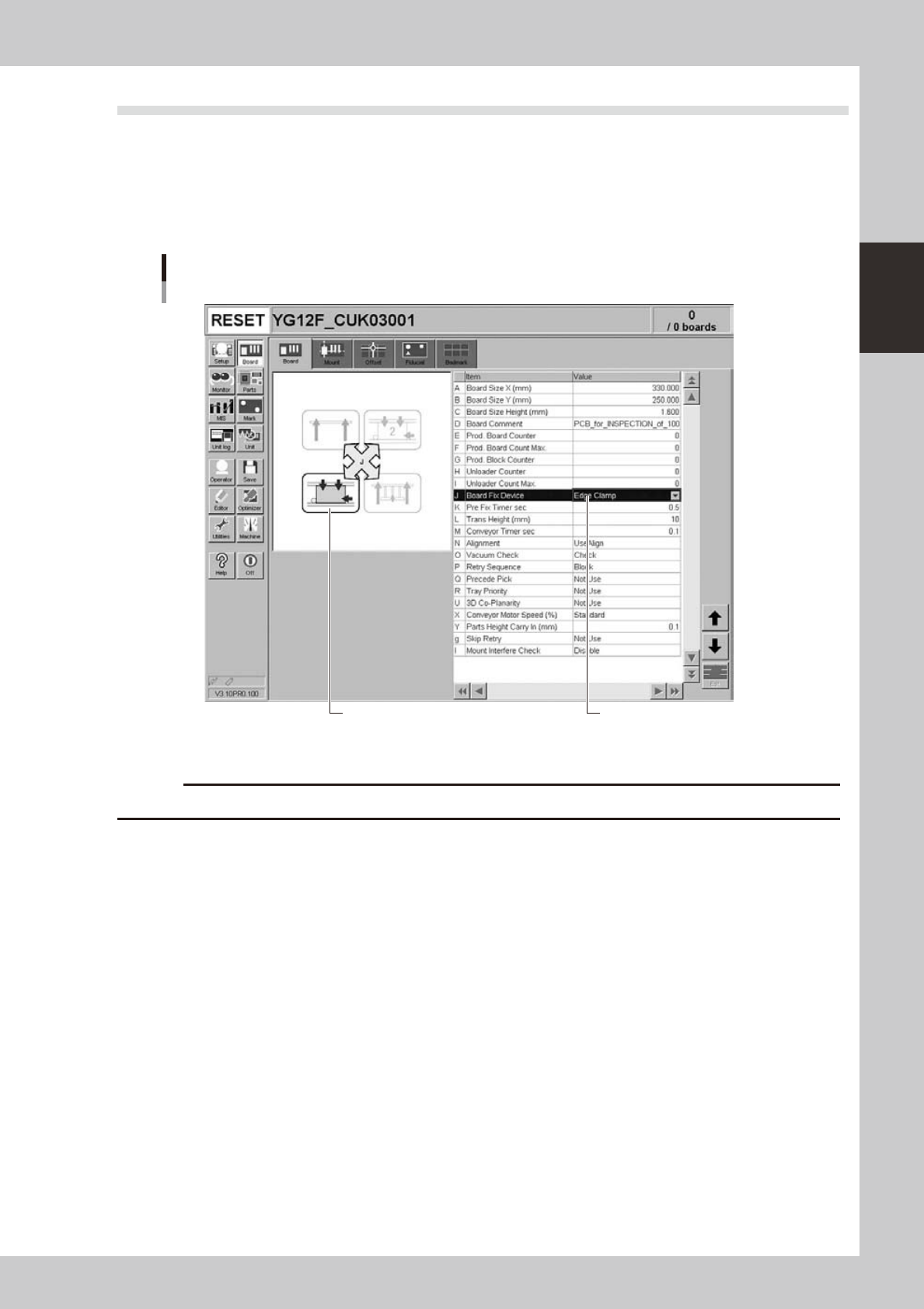
Board clamping method
Select "Edge Clamp" for the board clamping method. This method clamps a board by pushing up its edges against the
board hold plates. Push-up pins are also used to support the board at points other than its edges.
Board clamping method
Checking board clamp method
Illustration shows how board
is clamped on the conveyor.
24217-M7-00
c
Conveyor's board sensors may fail to detect a production board if it has a slit or cutout.
2-24
2
asic operation
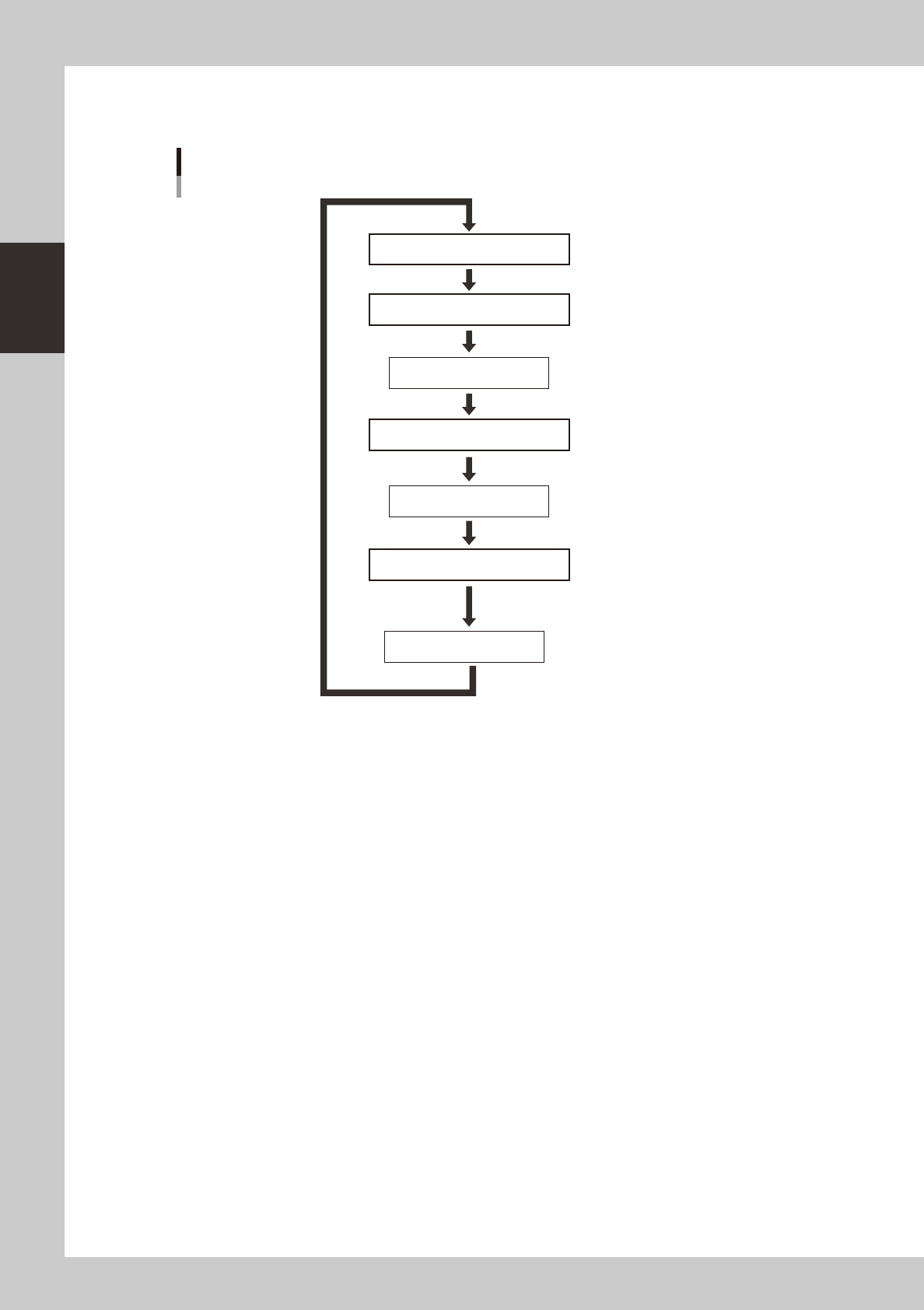
3.4.1 Conveyor unit setup flow
Set up the convey units as shown in the flowchart below.
Adjust conveyor width
Set board on conveyor
Press [Width] button.
Set push-up pins
Board is clamped
Raise push-up plate.
Lower push-up plate.
Check that board is clamped securely
Remove board
Press emergency stop button
Setup flow
Conveyor
23203-M7-00
1
Adjust the conveyor width.
After selecting the board data, open the [Unit]-[Conveyor] tab and press the [Width] button. Check the
conveyor width shown in the "Conveyor Width" dialog box that appears, and press the [OK] button. The
conveyor width changes to the specified width.
e
2
Press the emergency stop button and open the safety cover.
3
Set a board on the conveyor.
2-25
2
asic operation
4
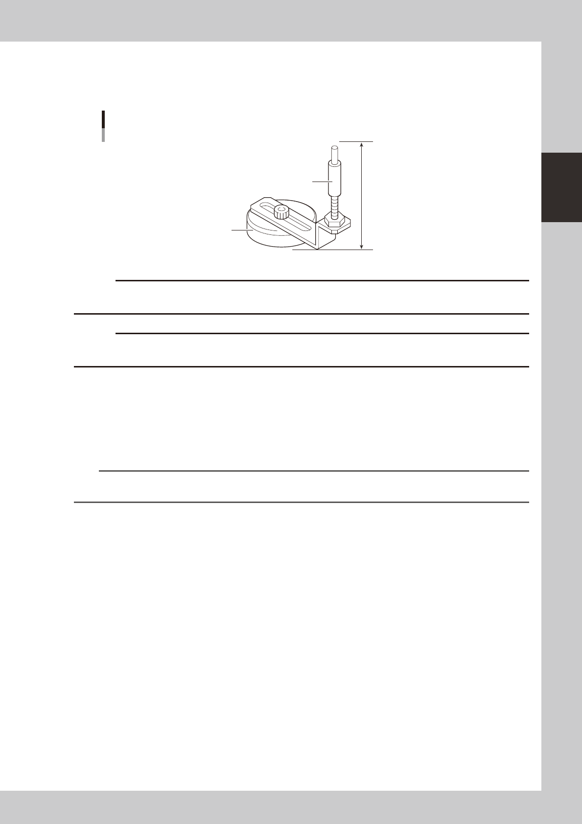
Place the push-up pins in the correct positions on the push-up plate.
Push-up pins are attached on the push-up plate by magnet. Considering the shape and size of the
board, place the push-up pins on the push-up plate so that they uniformly support the board, including
the edge of the board.
76mm
Support pin
Push-up pin
Magnet stand
23204-M7-00
c
height.
c
Set the push-up pins in positions where they will not interfere with the conveyor rails and other parts when the push-up
plate is raised.
5
Raise the push-up plate.
Check safety and press the [Push Up] button on the Setup screen. The push-up plate moves up to clamp
the board.
6
Check that the board is uniformly clamped on the conveyor.
Lightly tap on the board and also check for warping of the board from the side. If the board is
supported
evenly with no warping, the adjustment is okay.
TIP
It may be convenient to mark the positions of the push-up pins on the plate (with a label, magic marker, etc.) for each
board type.
7
Remove the board from the conveyor.
Press the [Push Up] button on the Setup screen to lower the push-up plate and then remove the board.