YG12F_Ope_E.pdf - 第39页
1-5 1 Part names and functions 3. Head assembly The head assembly is mounted on the XY arms and moves to pick up and place components. The following sections describe the head assembly configurations and nozzle types. He…
1-4
1
Part names and functions
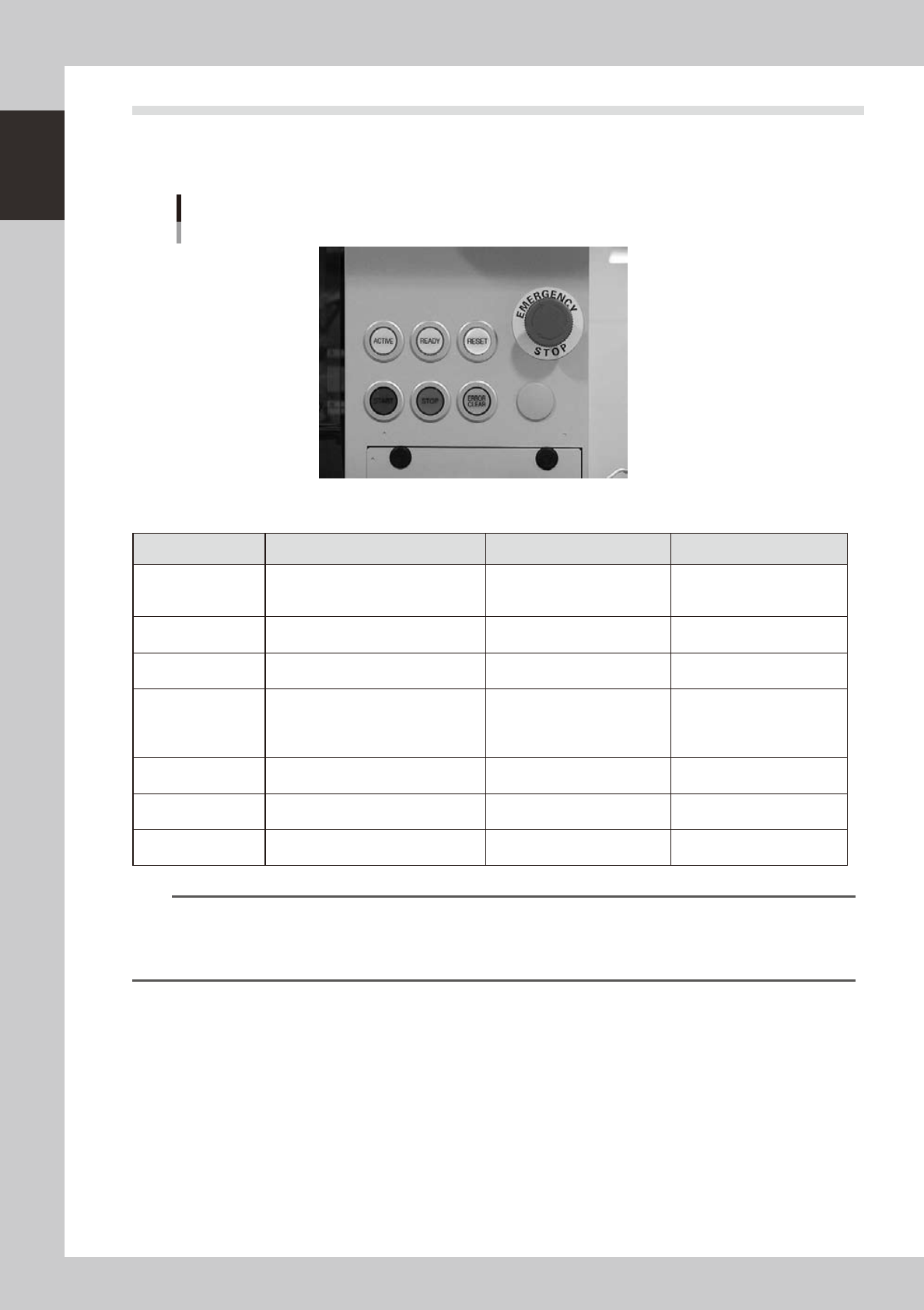
2.2 Operation panel buttons
The operation panel buttons are provided on the front and rear (option) of the machine to run major commands
frequently used to operate the machine. Each button is lit while turned on. (Colors of panel buttons are the
same as the colors specified for signal lights.)
Operation panel buttons
23103-M7-00
n
Operation panel button functions
Button name Use the button to: OFF ON
ACTIVE
Enable other keys. (The front and rear
[ACTIVE] keys cannot be turned on
simultaneously.)
• After machine has started.
• The other table has access
rights to operate machine.
• Has access rights to
operate machine.
READY
Release emergency stop and turn the
servo on.
• SERVO OFF
(Motor power OFF)
• SERVO ON
(Motor power ON)
RESET
Stop automatic operation and return to
standby for board production.
• Machine is in normal operation
or stopped.
• Machine has been reset.
START (green)
Perform component placement
according to board data.
• Machine is stopped.
• Machine is in normal
operation.
[Flash]
Pause or step operation
STOP (Red/White)
Interrupt automatic operation. (Press
START to resume operation.)
• Machine is in normal
operation.
• Error occurred.
ERROR CLEAR
(Yellow/Blue)
Stop buzzer sound and clear error
screen.
• Machine is in normal
operation.
• Error occurred.
EMERGENCY STOP
Trigger emergency stop. Turn to the
right to release it.
n
NOTE
The [ACTIVE] button is provided on both front and rear (option) panels, but cannot be turned on simultaneously. This
means that the [READY], [START], [ERROR CLEAR] and [RESET] buttons are enabled only when the [ACTIVE] key on the
same panel is turned on. (The [STOP] button can be used when the [ACTIVE] button is either on or off.)
The keyboard is enabled only when the [ACTIVE] key on the front panel is on.
1-5
1
Part names and functions
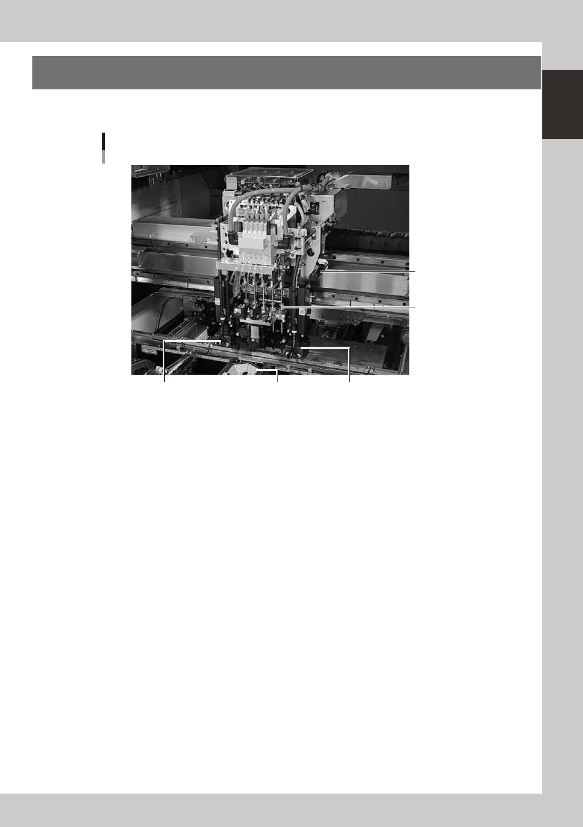
3. Head assembly
The head assembly is mounted on the XY arms and moves to pick up and place components. The following
sections describe the head assembly configurations and nozzle types.
Head assembly
Fiducial camera lighting unit (option)
Multi-vision camera
Fiducial camera lighting unit
5-in-line multi-head
Handle for moving
head assembly
23004-M7-00
1-6
1
Part names and functions
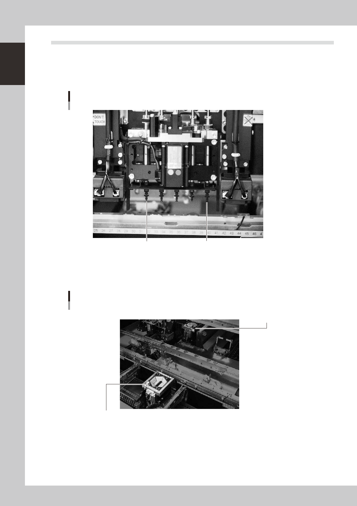
3.1 Component pick-and-place head
3.1.1 5-in-line multi-head assembly
The 5-in-line multi-head assembly has 5 heads arranged in a row to pick up and place components. Head
numbers are designated from 1 to 5, from the right as viewed from the front of the machine. The spacing of
adjacent nozzles attached to the head assembly is 24mm.
Head 5 Head 1
5-in-line multi-head assembly
23105-M7-00
3.1.2 Multi-vision camera
YG12F has a component recognition camera on the front side as standard equipment.
This camera can also be added to the rear side as an option.
Multi-vision camera
Rear multi-vision camera
(option)
Front multi-vision camera
23106-M7-00