00197402-01 AI X-Feeder Upgrade Package.pdf - 第30页
X-Feeder Upgrade Install Remove the screws on the right side of the feeder 30 AI X-Feeder Upgrade Package AI X-Feeder Upgrade Packa ge 3.3 3 . 3 R e m o v e t h e s c r e w s o n t h e r ig h t s id e o f t h e f e e d e…
X-Feeder Upgrade Install
Removing the Left Side Cover
AI X-Feeder Upgrade Package AI X-Feeder Upgrade Package 29
3
3 X-Feeder Upgrade Install
X-Feeder Upgrade Install
3.1
3.1 Removing the Left Side Cover
Removing the Left Side Cover
3.2
3.2 Remove the cable connection to the distribution board
Remove the cable connection to the distribution board
Tools required:
▪ Phillips screwdriver
▪ TORX screwdriver size T8
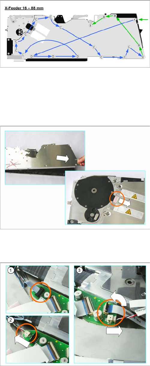
► Carefully place the feeder module with the right-side
side down on a stable, level and clean surface.
► Loosen the screws as shown in the diagram.
Green arrows point to the screws for which you need a
TORX screwdriver with a torque of 0.6 Nm.
Blue arrows point to the screws for which you need a Phil
-
lips screwdriver with a torque of 0.9 Nm.
Start to loosen the screws at the position shown by the
green arrow.
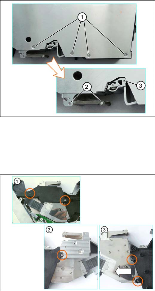
► Lift the back of the side cover.
► Pull the side cover at a slight angle towards the back.
Make sure that you pull the lug straight out of the
drive unit.
► Place the side cover down on a clean, safe surface.
► (1) Pull the connector marked in the diagram up and
out of its connection.
To loosen the connector, move it carefully from side
to side.
► (2) Pull the connector marked in the diagram out of its
connection in the direction of the arrow. Pull on the
connector and NOT on the cable.
► (3) Carefully swing the lock on the flat ribbon cable
connection up to the left and release the flat ribbon
cable.
Make sure that the lock is not pushed too far back. It
could break off if you do this.
► Pull the connector shown in the diagram out of its
connection in the direction of the arrow. Pull on the
connector and NOT on the cable.
X-Feeder Upgrade Install
Remove the screws on the right side of the feeder
30 AI X-Feeder Upgrade Package AI X-Feeder Upgrade Package
3.3
3.3 Remove the screws on the right side of the feeder
Remove the screws on the right side of the feeder
3.4
3.4 Dismantle of foil drive
Dismantle of foil drive
Tools required:
▪ Flat bladed (slotted) screwdriver
▪ hexagon socket 2
▪ TORX screwdriver size T8
▪ Split pin punch 1.4
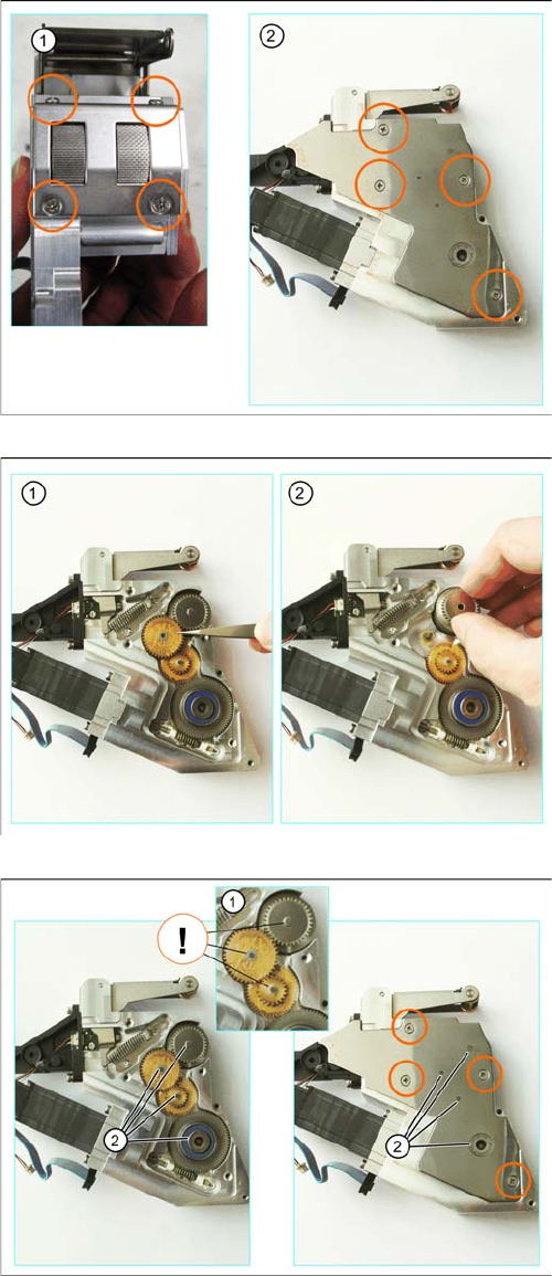
► Carefully place the feeder module down on its left
side.
► (1) Loosen the screws of the foil container.
► (2) Remove the shaft and roller of the cover strip
rocker.
► (3) Press the rocker as far till it stop, into the spring,
to relieve the bearing shaft.
► Release the bearing shaft and remove the rocker.
Place the feeder carefully on a protected and cleaned
place.
Tools required:
▪ Phillips screwdriver
▪ TORX screwdriver size T8
► (1) Loosen the screws marked in the diagram.
► Turn the foil disposal drive over.
► (2) Loosen the screw marked in the diagram.
► (3) Loosen the screws marked in the diagram.
X-Feeder Upgrade Install
Replacing the stuffing gear and parts of the cover strip rocker
AI X-Feeder Upgrade Package AI X-Feeder Upgrade Package 31
3.5
3.5 Replacing the stuffing gear and parts of the cover strip rocker
Replacing the stuffing gear and parts of the cover strip rocker
Tools required:
▪ Hexagon socket Gr. 2
▪ Phillips screwdriver
▪ Flat bladed (slotted) screwdriver
▪ Tweezers
► (1) Loosen the screws marked in the figure, at the top
and bottom of the stripping device. Depending on the
width of the feeder module, there will be up to a total
of 4 screws to be loosened at the top and bottom.
► (2) Loosen the screws on the cover sheet of disposal
drive.
► Lift the cover plate off the foil disposal drive.
► (1) Lift the gear stages with tweezers from the foil dis
-
posal drive.
Attention: The stage gear is greasy!
► (2) Remove the knurled stuffing gear and replace it
with the new "interlocked complete stuffing gear."
► Make sure that the corresponding washers are on the
toothed wheel axes (1).
► Place the cover plate on the slide disposal drive.
Make sure that the cover plate engages on the
toothed wheel axes (2) and the cover plate lies flat
level on the side cover.
► Fix the cover plate with the countersunk screws
marked in the diagram.