00197469-02_SM_Twin_Kunde_EN.pdf - 第48页
4 Pneumatic and pressure control valve (PRV) 4.7 Replacing the pneumatic rotary supply 48 Service Manual SIPLACE TwinStar (Twin, Twin HF, Twin VHF) 07/2020 Fig.73: Removing the pneumatic rotary supply ► Pull the pneumat…
4 Pneumatic and pressure control valve (PRV)
4.7 Replacing the pneumatic rotary supply
Service Manual SIPLACE TwinStar (Twin, Twin HF, Twin VHF) 07/2020 47
4.7 Replacing the pneumatic rotary supply
Parts
●
Pneumatic rotary supply [03004609Sxx] incl. hose and screws (suitable for all Twin types)
●
Seal for sleeve with ball fixing P&P module [03020698‑xx] (suitable for all Twin types)
When replacing the pneumatic, also replace the seal, as this keeps the rotary supply tube
centrally aligned to the sleeve with ball fixing.
Overview
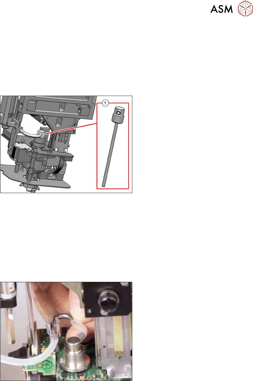
Fig.71: Pneumatic rotary supply
1. Pneumatic rotary supply [03004609-xx]
Preparation
► Remove the head from the machine. For details about removing and fitting the placement
head, refer to the service manual for your machine.
Removal
► Dismantle the buffer.
3.1 "Replacing the return unit buffer" [}17]
► Dismantle the sleeve with ball fixing.
4.6 "Replacing the sleeve with ball fixing/seal" [}43]
Fig.72: Disconnecting the hose
► Disconnect the short hose from the el-
bow.
4 Pneumatic and pressure control valve (PRV)
4.7 Replacing the pneumatic rotary supply
48 Service Manual SIPLACE TwinStar (Twin, Twin HF, Twin VHF) 07/2020
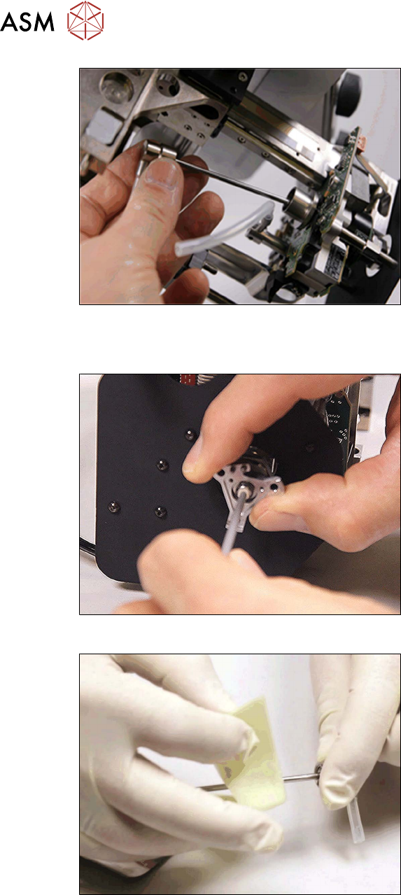
Fig.73: Removing the pneumatic rotary supply
► Pull the pneumatic rotary supply out of
the DP unit.
Installation
Fig.74: Cleaning the pneumatic rotary supply seat 1
► Clean the inside of the DP station shaft
with a cotton swab soaked in isopro-
panol.
Clean both sides as the cotton swab
will not be able to get fully into the guid-
ance from just one side.
Fig.75: Cleaning the pneumatic rotary supply
► Clean the shaft of the pneumatic rotary
supply.
4 Pneumatic and pressure control valve (PRV)
4.7 Replacing the pneumatic rotary supply
Service Manual SIPLACE TwinStar (Twin, Twin HF, Twin VHF) 07/2020 49
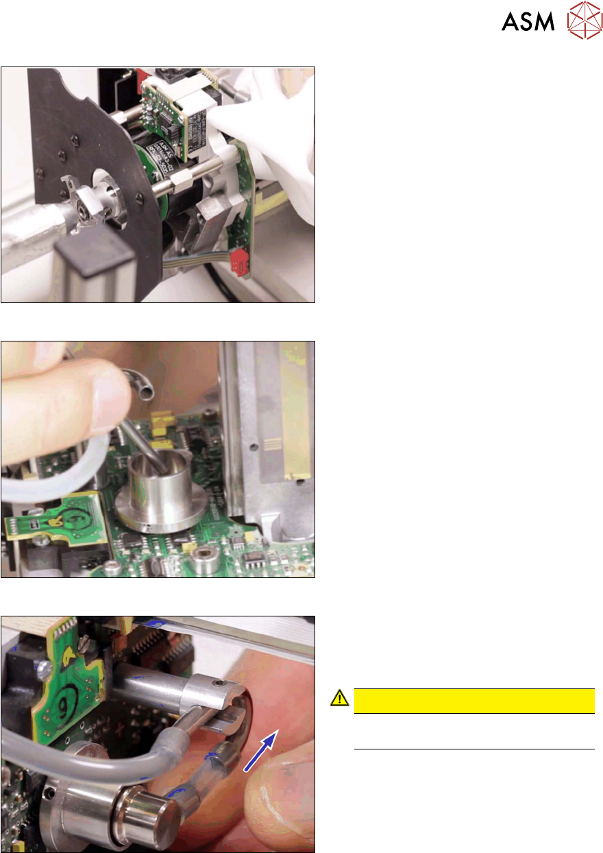
Fig.76: Cleaning the pneumatic rotary supply seat 2
► Clean the seat with compressed air.
Cover the outlet on the other side while
doing this.
Fig.77: Inserting the pneumatic rotary supply
► Insert the new pneumatic rotary supply
into the seat.
Fig.78: Silicone hose 4.5x2.5x26
► Fit the hose from the pneumatic rotary
supply onto the elbow. Connect the
hose so that no tension is applied to
the pneumatic rotary supply.
CAUTION!
The new hose must be mounted abso-
lutely twist-free!
.