00197469-02_SM_Twin_Kunde_EN.pdf - 第53页
4 Pneumatic and pressure control valve (PRV) 4.8 Replacing the force measuring unit and the trick and feather unit Service Manual SIPLACE TwinStar (Twin, Twin HF, Twin VHF) 07/2020 53 Fig.88: Removing the cable guide ► …
4 Pneumatic and pressure control valve (PRV)
4.8 Replacing the force measuring unit and the trick and feather unit
52 Service Manual SIPLACE TwinStar (Twin, Twin HF, Twin VHF) 07/2020
4.8.2 Removal
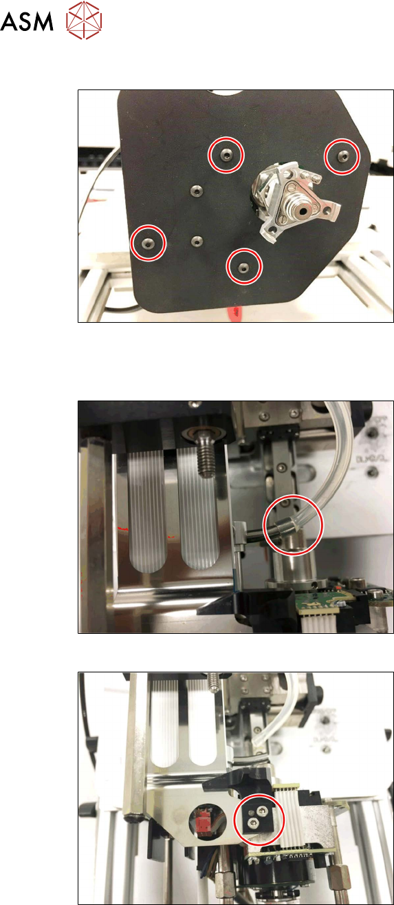
Fig.85: Screws fastening the camera lens hood
► Remove the four fastening screws and
take off the camera lens hood.
► Dismantle the buffer on the return unit.
3.1 "Replacing the return unit buffer" [}17]
Fig.86: Hose on the pneumatic rotary supply
► Pull the hose off the pneumatic rotary
supply.
Fig.87: Removing the return unit end stop
► Remove the two screws and then
remove the return unit end stop.
4 Pneumatic and pressure control valve (PRV)
4.8 Replacing the force measuring unit and the trick and feather unit
Service Manual SIPLACE TwinStar (Twin, Twin HF, Twin VHF) 07/2020 53
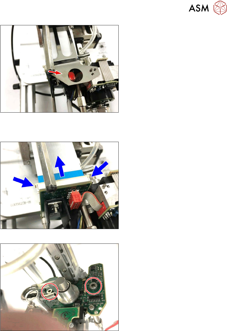
Fig.88: Removing the cable guide
► Remove the cable guide for the flex-
print cable.
► Dismantle the hose guidance, the flat ribbon baffle and the stopper.
3.3 "Replacing the hose and flat ribbon guide (Twin HF only)" [}23]
Fig.89: Disconnect the control cable
► Open the lock on the control cable and
disconnect the control cable.
Fig.90: Screw fastening the force measuring board
► Remove the two screws fastening the
TwinHead force measuring unit.
4 Pneumatic and pressure control valve (PRV)
4.8 Replacing the force measuring unit and the trick and feather unit
54 Service Manual SIPLACE TwinStar (Twin, Twin HF, Twin VHF) 07/2020
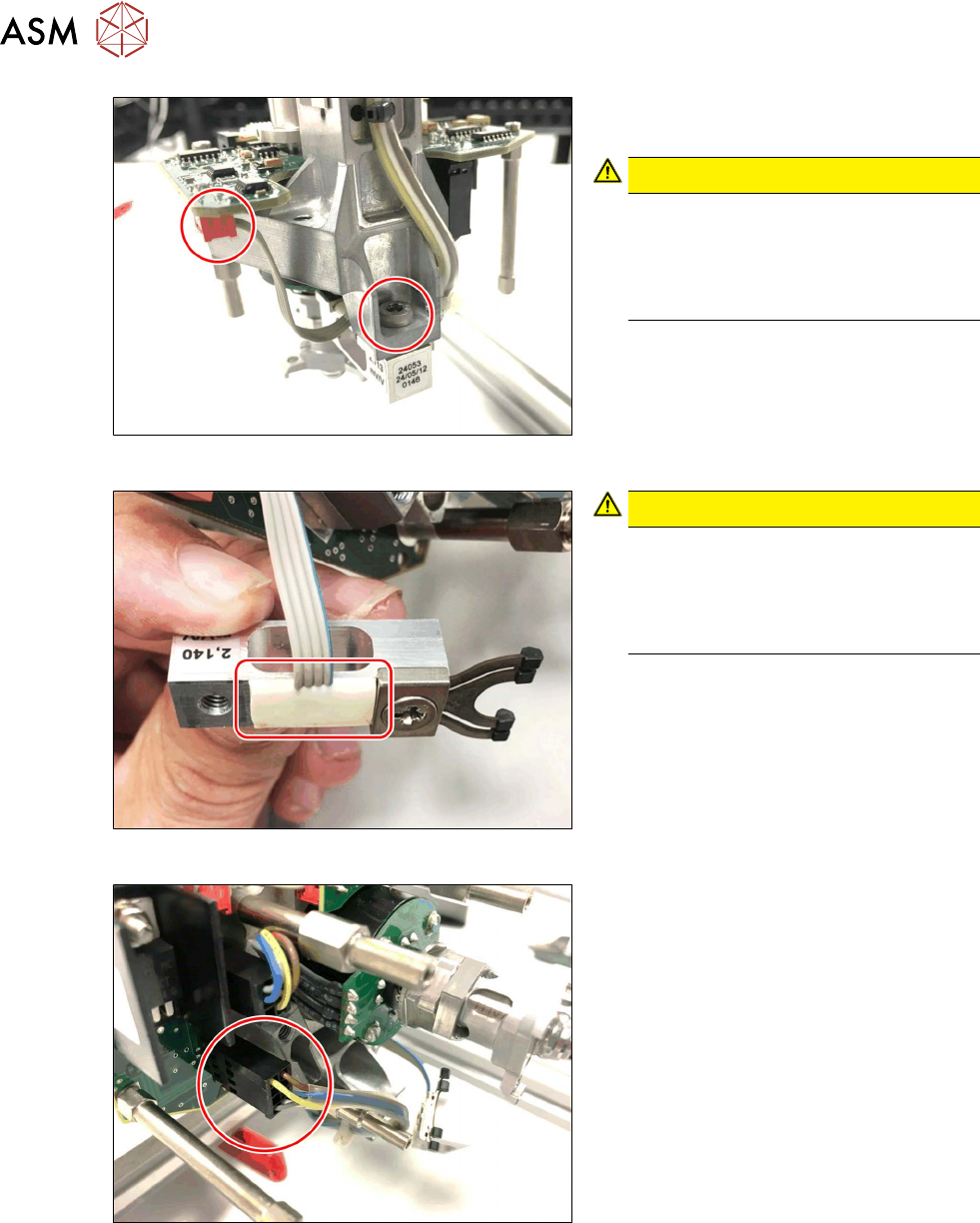
Fig.91: Dismantle the power sensor
► Remove the screws fastening the
power sensor.
CAUTION!
Do not damage the power sensor!
The power sensor stays connected to
the TwinHead force measuring unit.
Take particular care when performing
the following steps.
.
Fig.92: Power sensor
CAUTION!
Do not damage the power sensor!
The power sensor cable is fixed to the
housing with silicone.
Take care not to damage the power
sensor and the cable.
.
Fig.93: Z axis motor connector
► Unplug the Z axis motor.