00197469-02_SM_Twin_Kunde_EN.pdf - 第62页
4 Pneumatic and pressure control valve (PRV) 4.8 Replacing the force measuring unit and the trick and feather unit 62 Service Manual SIPLACE TwinStar (Twin, Twin HF, Twin VHF) 07/2020 Fig.113: Fitting the old holder and…
4 Pneumatic and pressure control valve (PRV)
4.8 Replacing the force measuring unit and the trick and feather unit
Service Manual SIPLACE TwinStar (Twin, Twin HF, Twin VHF) 07/2020 61
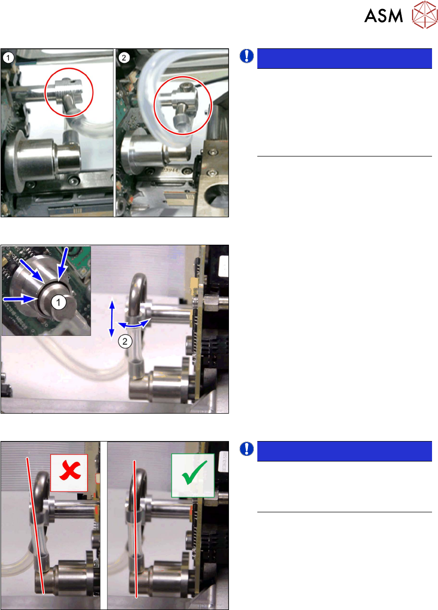
Fig.110: Holder and pipe clamp versions
NOTICE!
Different holder and pipe clamp ver-
sions!
There are two different versions of the
holder and pipe clamp. These are also
set differently.
(1) Old version (loose)
(2) New version (fixed)
.
Fig.111: Fitting the new holder and pipe clamp
New holder and pipe clamp
► Connect the hoses to the holder, pipe
clamp and rotary supply.
► Attach the holder and pipe clamp and
fix into place with a screw.
► Set the hose(2) so that this runs dir-
ectly between the rotary supply and the
holder plus pipe clamp.
► The rotary supply(1) must sit in the
center of the fly wheel without exerting
any side forces.
Fig.112: Check the new holder and pipe clamp
NOTICE!
Check the new holder and pipe
clamp!
Make sure that the hose runs parallel
to the pipes.
.
4 Pneumatic and pressure control valve (PRV)
4.8 Replacing the force measuring unit and the trick and feather unit
62 Service Manual SIPLACE TwinStar (Twin, Twin HF, Twin VHF) 07/2020
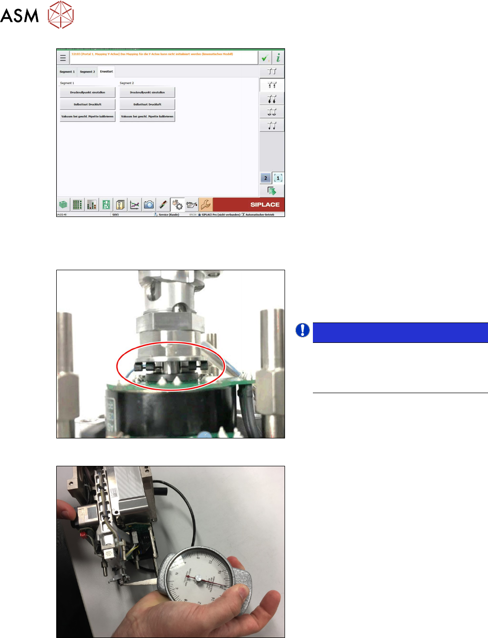
Fig.113: Fitting the old holder and pipe clamp
Old holder and pipe clamp
► Insert the holder and pipe clamp into
the mount so that the end of the pipe
faces upwards.
► Fix the holder and pipe clamp into
place with the grub screw.
► Connect the hoses to the holder, pipe
clamp and pneumatic rotary supply.
► Set the hose(2) so that this runs
straight between the pneumatic rotary
supply and the holder plus pipe clamp.
► The pneumatic rotary supply(1) must
sit in the center of the fly wheel without
exerting any side forces.
4.8.4 Setting the force measuring unit
Fig.114: Setting the force measuring unit
► Set the actuator of the force measuring
unit so that it is centered and parallel.
To do this, move the plate, which holds
the actuator in place, back and forth.
NOTICE!
Observe the position of the pins!
The actuator pins must be aligned
straight to the connection disk on both
sides.
.
Fig.115: Set the Z axis
► Use a spring-type dial gauge to press
the Z axis until the inner pins touch the
contact disk.
Target value when touching: 20N
► If not: use adjustment shims to adjust
the setting and repeat the measure-
ment.
► Fit the buffer on the return unit.
3.1 "Replacing the return unit buffer" [}17]
4 Pneumatic and pressure control valve (PRV)
4.8 Replacing the force measuring unit and the trick and feather unit
Service Manual SIPLACE TwinStar (Twin, Twin HF, Twin VHF) 07/2020 63
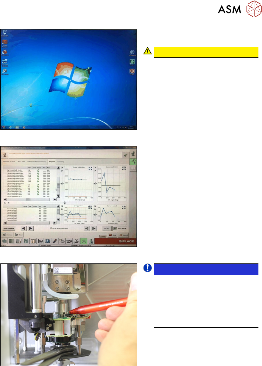
Fig.116: Start the software
► Fit the Twin module to the SIPLACE
Head Care Station.
CAUTION!
User guide
Observe also the user guide for the
SIPLACE Head Care Station.
.
► Start the software and run a calibration
of the force measuring unit and a 1N
measurement.
Fig.117: Perform measurement
► Check whether the preset spring values
are within the target range.
► If one or more values are outside the
target range, reset the dual rotating
disk.
Fig.118: Highlight
NOTICE!
Fix the clamp!
The dual rotating disk and the counter-
nut are highly sensitive parts.
Tighten these until you notice that the
force needed has increased slightly.
Tighten slightly more.
Mark the setting direction.
.