cp45头部故障判断.pdf - 第24页
1. Head Module Ver. Date CP45 CP45NEO 00 2004/11 O O 1-1 1-12. Nozzle Check Fu nction Setting (for Former Serial No ~1188 Equipment) *T o o l s a) 1-12-1) When Using Nozzle Check Sensor 1-12-1-1) Select I/O Test of Diagn…
1. Head Module
Ver. Date CP45
CP45NEO
00 2004/11 O O
1-1
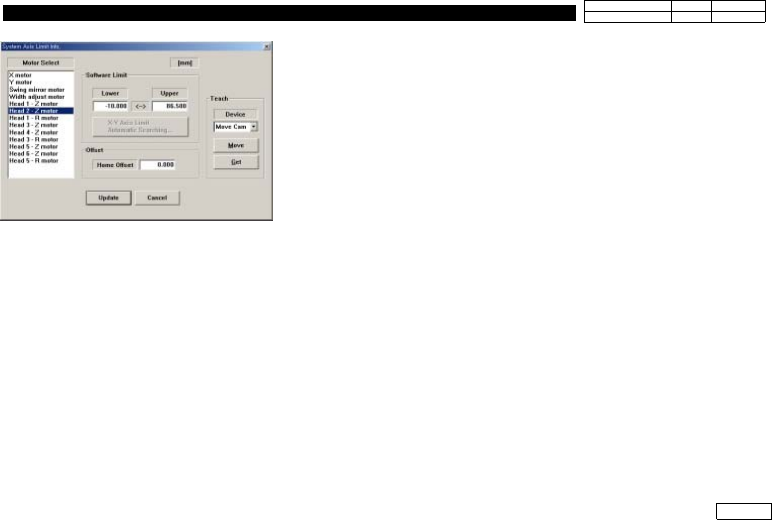
1-11.Offset-R Adjustment and Input
*Tools
a)
*Part
a)
.
=> Used for FV Type
1) Run R-axis Home
2) Move Axis(1-2 ,3-4, 5-6) to be Measured to Stage Camera
(Select Sys. Setup => Camera => Stage Camera => Camera Position to Move)
3) Arrange the Groove of Nozzle Holder with low speed of Teaching Box Watching Monitor,
andCheckthePositionofR-axisat'CurrentPosition'
4)
Input This Value at Head Z-Motor Offset for Compensation (Ref. Fig 1-11-1)
(Compensation Value Check at Current Position is Added with '-' and Inputted)
Fig1-11-1HeadZHomeOffset
1. Head Module
Ver. Date CP45
CP45NEO
00 2004/11 O O
1-1
1-12. Nozzle Check Function Setting (for Former Serial No ~1188 Equipment)
*Tools
a)
1-12-1) When Using Nozzle Check Sensor
1-12-1-1) Select I/O Test of Diagnosis Menu to Check if Nozzle Check Sensor Works
- Turn Sensor ON/OFF with Mouse to Check
- Check ON/OFF by Covering Sensor with Paper (Check Assembled Condition)
1-12-1-2) Insert TN05 in HEAD3 (Use PICK Function of ANC)
- Note : Don't Insert Manually
1-12-1-3) Open Menu - View - Current position
1-12-1-4) Lower Head to 60mm with Teaching Box
1-12-1-5) Change the Switch of Sensor Amp to Set Mode
1-12-1-6) Turn the Switch of Sensor Amp ON
1-12-1-7) Lower Head3 to 50mm with Teaching Box
1-12-1-8) Turn the Switch of Sensor Amp OFF
1-12-1-9) Change the Switch of Sensor Amp to Run Mode
1-12-1-10) Slowly Move Head3 to 57mm (with Teaching Box)
Setting is OK if Green and Red LED are Both ON at 57.0 ~ 58.0mm.
Only Green LED is ON if Head3 Keeps Going Down
Reset from 1-12-1-4) if Green LED is OFF or Red LED is ON
- Increase the Height of Head3 in 1-12-1-7) by 1mm for Setting
- If the Height is Increased to 55.0mm in 1-12-1-7) and There is No Change of Sensing
Distance, Use it w/o Further Change
1-12-1-11) Check if Sensor Works at ANC Screen
IfArbitraryHeadw/oNozzleisUsedtoSelectArbitraryANCNumberw/oNozzleand
PICK is Clicked, in Normal Case the Error Message that There is No Nozzle in Head is
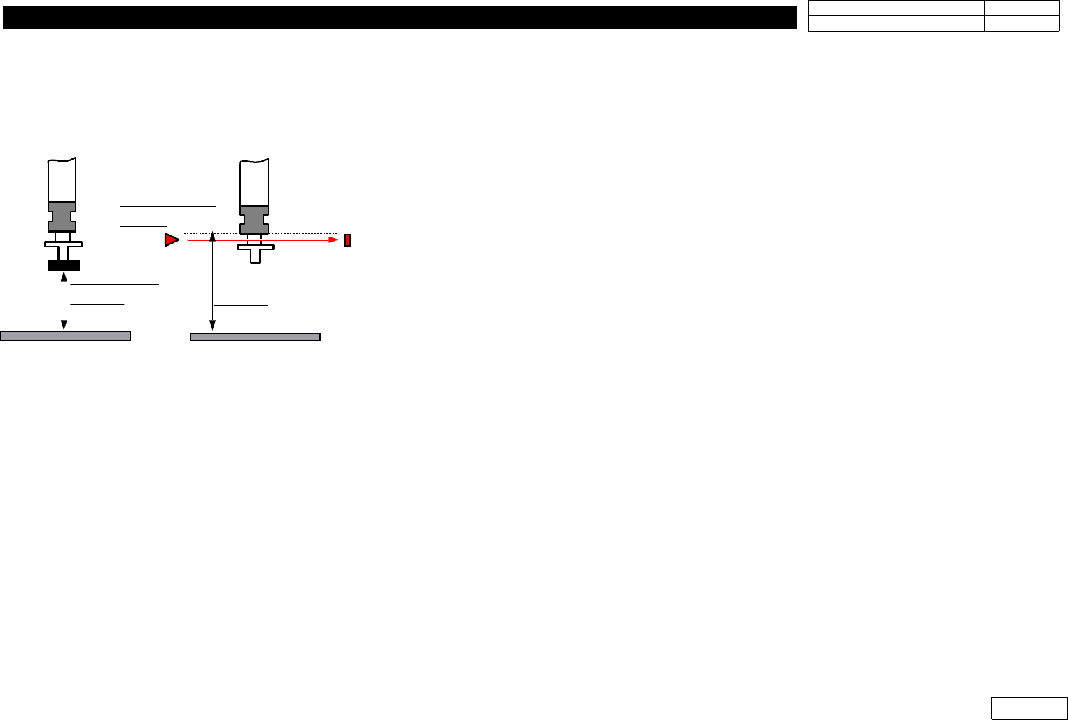
ALIGN HEIGHT
=54.5mm
PCB PCB
NOZZLE CHECK HEIGHT
=59.0mm
NOZZLE CHECK
SNESOR
Fig.1-12
Nozzle Check Sensor setting.
1. Head Module
Ver. Date CP45
CP45NEO
00 2004/11 O O
1-1
Displayed on Screen.
In Abnormal Case, Redo the Procedure Above Again
1-12-2) Nozzle Check with Vision
Set as Following Procedure
1-12-2-1) Prerequisite
1) Only Available for the Equipment over MMI Version 2450
2) Nozzle Check of Products after Serial No. 1188 is Available Only with Vision
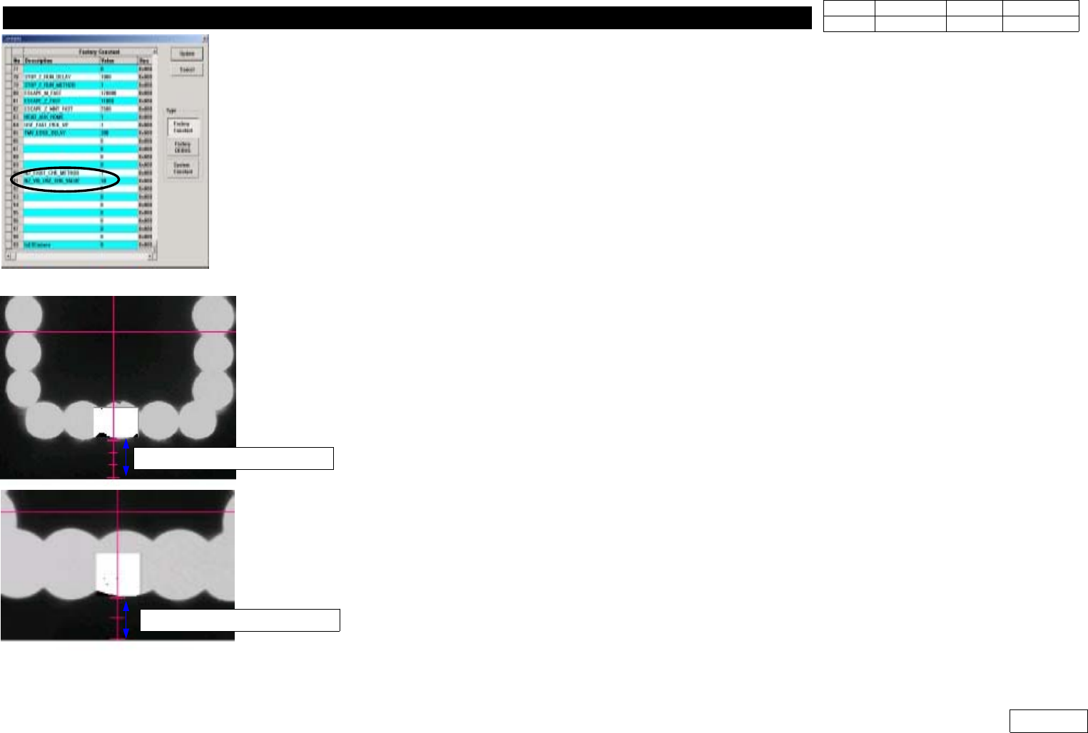
1-12-2-2) Factory Setup Modification (Fig 1-12-2--1)
Set Binary Pixel Count Value => #90, #91 Items
90) NZ_EXIST_CHK_METHOD : Set Vision Use:1, Sensor Use:0
(Only Products before Serial 1188)
91) NZ_VIS_USE_CHK_VALUE : Set 30
1-12-2-3) System Setup
For System Setup, Set Conditions to Sense the Existence of Nozzle with Flying Camera
- Check Pos. Mirror
Set the Angle(deg) of Mirror to Check the Existence of Nozzle
If FOV is 25mm, Make Fourth Graduation under Y-center Axis of Vision and Lower Part of
Outer Light Coincide with Each Other (Ref. Fig 2-12-2-3)
If FOV is 15mm, Make Third Graduation under Y-center Axis of Vision and Outer Light
Coincide with Each Other (Ref. Fig 2-12-2-3)
1-12-2-5) Check Pos. Z
Set the Height of Z-axis(mm) to Sense the Existence of Nozzle
After Removing Nozzle, Make the Position of End Part of Nozzle Holder Coincide with Fourth
Graduation under Y-center Axis of Vision(for FOV 25mm) and the Lower Part of Outer Light
Fig.1-12-2-1 Factory setup
Fig.1-12-2-2 Check pos. Mirror
FOB 25mm =>4 scale
FOB 15mm =>3 scale