cp45头部故障判断.pdf - 第25页
1. Head Module Ver. Date CP45 CP45NEO 00 2004/11 O O 1-1 Displa yed on Screen. In Abnormal Ca se, Redo the Pr ocedure Abo ve Again 1-12-2) Nozzle Check with Vision Set as Following Proc edure 1-12-2-1) Prerequisi te 1) O…
1. Head Module
Ver. Date CP45
CP45NEO
00 2004/11 O O
1-1
1-12. Nozzle Check Function Setting (for Former Serial No ~1188 Equipment)
*Tools
a)
1-12-1) When Using Nozzle Check Sensor
1-12-1-1) Select I/O Test of Diagnosis Menu to Check if Nozzle Check Sensor Works
- Turn Sensor ON/OFF with Mouse to Check
- Check ON/OFF by Covering Sensor with Paper (Check Assembled Condition)
1-12-1-2) Insert TN05 in HEAD3 (Use PICK Function of ANC)
- Note : Don't Insert Manually
1-12-1-3) Open Menu - View - Current position
1-12-1-4) Lower Head to 60mm with Teaching Box
1-12-1-5) Change the Switch of Sensor Amp to Set Mode
1-12-1-6) Turn the Switch of Sensor Amp ON
1-12-1-7) Lower Head3 to 50mm with Teaching Box
1-12-1-8) Turn the Switch of Sensor Amp OFF
1-12-1-9) Change the Switch of Sensor Amp to Run Mode
1-12-1-10) Slowly Move Head3 to 57mm (with Teaching Box)
Setting is OK if Green and Red LED are Both ON at 57.0 ~ 58.0mm.
Only Green LED is ON if Head3 Keeps Going Down
Reset from 1-12-1-4) if Green LED is OFF or Red LED is ON
- Increase the Height of Head3 in 1-12-1-7) by 1mm for Setting
- If the Height is Increased to 55.0mm in 1-12-1-7) and There is No Change of Sensing
Distance, Use it w/o Further Change
1-12-1-11) Check if Sensor Works at ANC Screen
IfArbitraryHeadw/oNozzleisUsedtoSelectArbitraryANCNumberw/oNozzleand
PICK is Clicked, in Normal Case the Error Message that There is No Nozzle in Head is
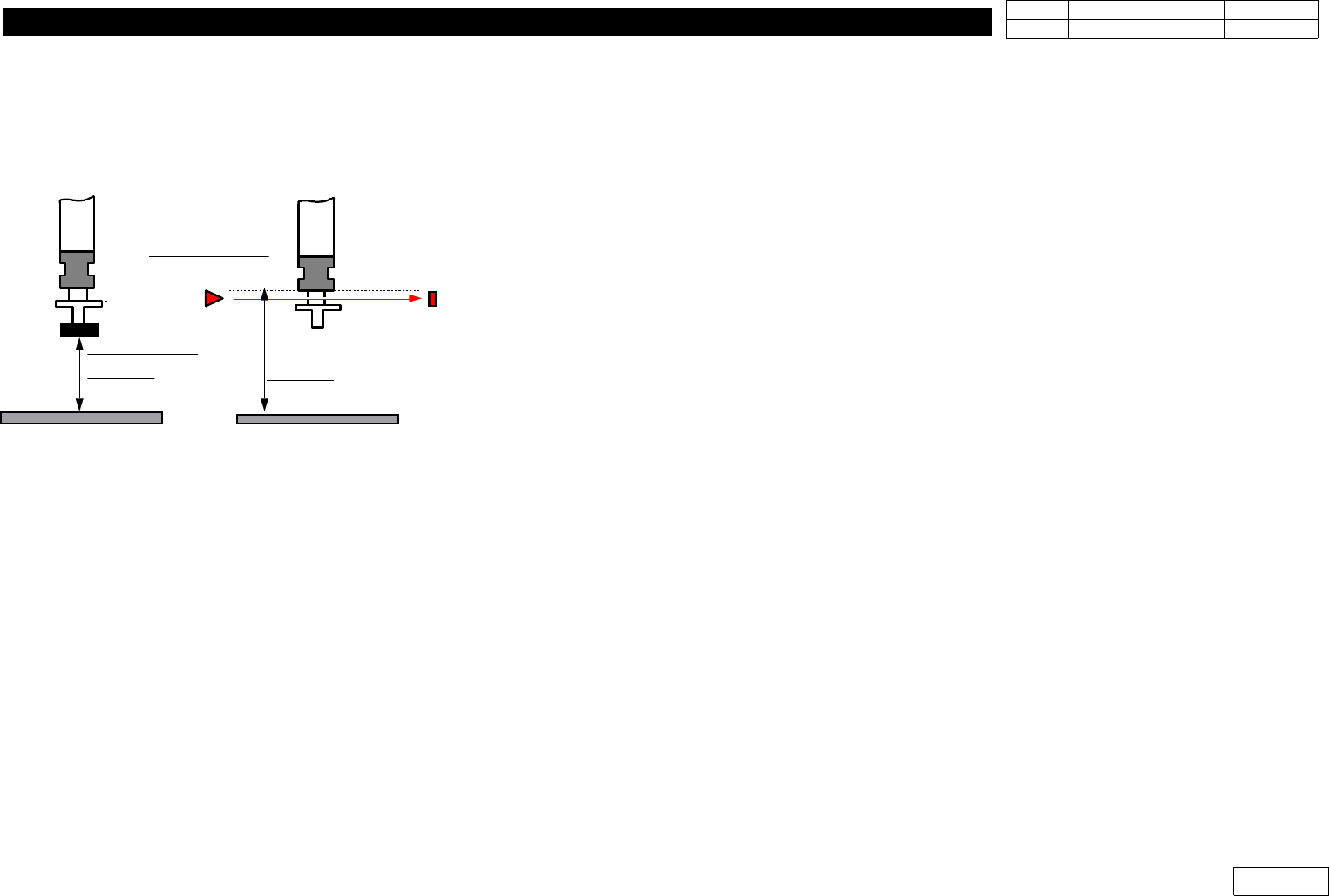
ALIGN HEIGHT
=54.5mm
PCB PCB
NOZZLE CHECK HEIGHT
=59.0mm
NOZZLE CHECK
SNESOR
Fig.1-12
Nozzle Check Sensor setting.
1. Head Module
Ver. Date CP45
CP45NEO
00 2004/11 O O
1-1
Displayed on Screen.
In Abnormal Case, Redo the Procedure Above Again
1-12-2) Nozzle Check with Vision
Set as Following Procedure
1-12-2-1) Prerequisite
1) Only Available for the Equipment over MMI Version 2450
2) Nozzle Check of Products after Serial No. 1188 is Available Only with Vision
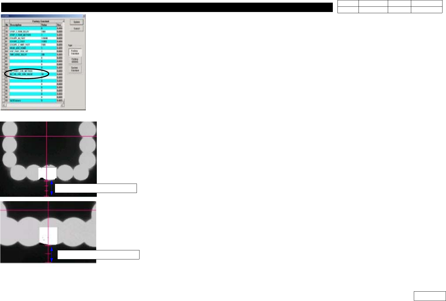
1-12-2-2) Factory Setup Modification (Fig 1-12-2--1)
Set Binary Pixel Count Value => #90, #91 Items
90) NZ_EXIST_CHK_METHOD : Set Vision Use:1, Sensor Use:0
(Only Products before Serial 1188)
91) NZ_VIS_USE_CHK_VALUE : Set 30
1-12-2-3) System Setup
For System Setup, Set Conditions to Sense the Existence of Nozzle with Flying Camera
- Check Pos. Mirror
Set the Angle(deg) of Mirror to Check the Existence of Nozzle
If FOV is 25mm, Make Fourth Graduation under Y-center Axis of Vision and Lower Part of
Outer Light Coincide with Each Other (Ref. Fig 2-12-2-3)
If FOV is 15mm, Make Third Graduation under Y-center Axis of Vision and Outer Light
Coincide with Each Other (Ref. Fig 2-12-2-3)
1-12-2-5) Check Pos. Z
Set the Height of Z-axis(mm) to Sense the Existence of Nozzle
After Removing Nozzle, Make the Position of End Part of Nozzle Holder Coincide with Fourth
Graduation under Y-center Axis of Vision(for FOV 25mm) and the Lower Part of Outer Light
Fig.1-12-2-1 Factory setup
Fig.1-12-2-2 Check pos. Mirror
FOB 25mm =>4 scale
FOB 15mm =>3 scale
1. Head Module
Ver. Date CP45
CP45NEO
00 2004/11 O O
1-1
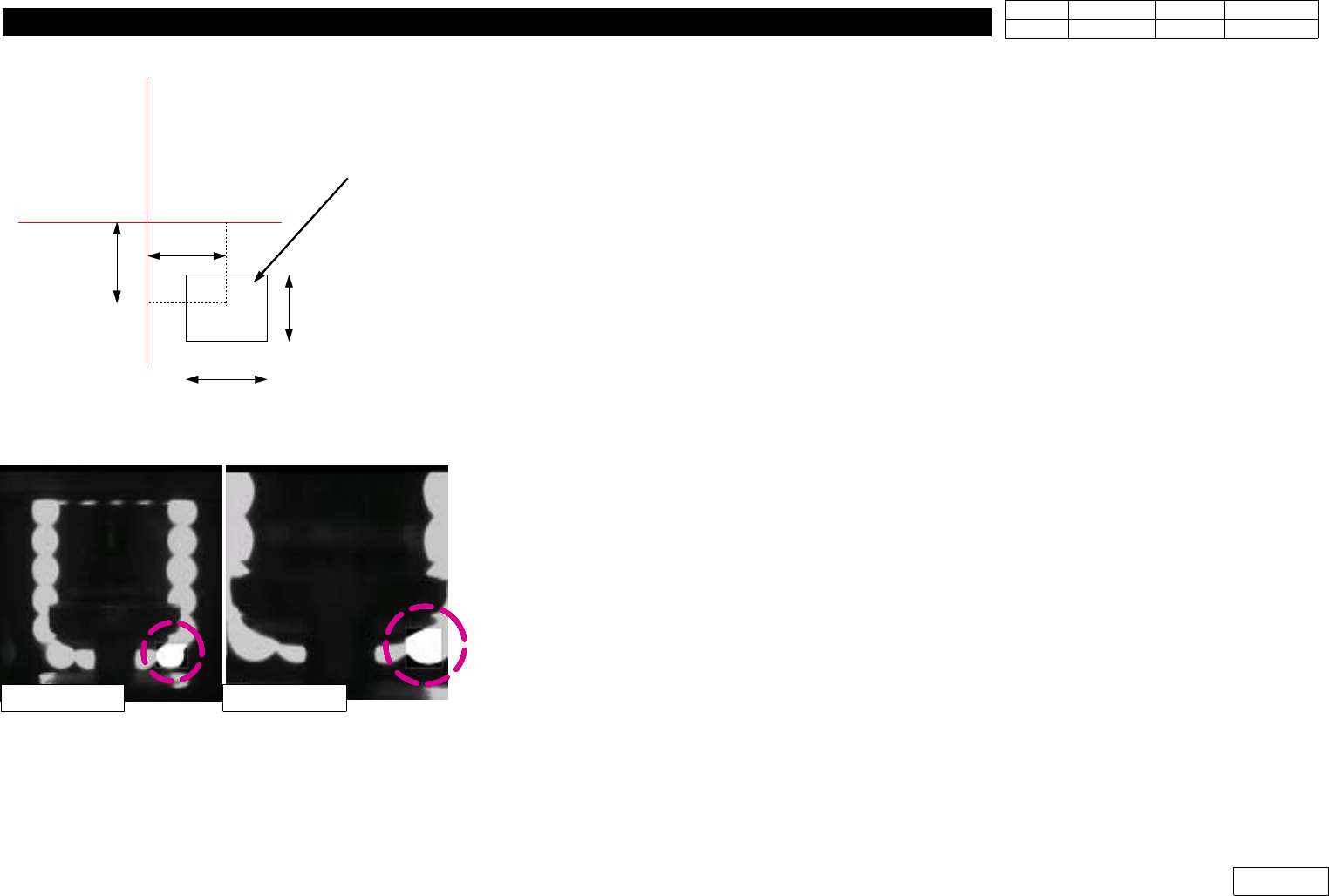
1-12-2-6) Nozzle( OffsetX, OffsetY, CountX, CountY )
Set Check Range(mm) to Check the Existence of Nozzle
OffsetX, OffsetY are Offset from Vision Center to the Center of Check Range
CountX, CountY are Width and Height of Check Range (Fig 1-12-2-4)
1-12-2-7) Light( OffsetX, OffsetY, CountX, CountY )
Set Check Range(mm) to Check the Existence of Light.
Check this Range with the Biggest Nozzle Connected.
The Light is ON if the Value of this Range is over 30%, and OFF if under 30%. (Fig 1-12-2-5)
1-12-2-8) Threshold
The Value is btw. Standard 0 and 255 to Distinguish White Pixel from Black Pixel when Calculating
Binary Pixel Count.
Default is 100.
1-12-2-9) Outer, Inner
SetLightConditiontobeUsedtoChecktheExistenceofNozzleandLight
Set Outer Light for the Mostly Used One and
Default to be Outer:3, Inner:0.
1-12-2-10) Nozzle Exist Value
Standard Value of Binary Pixel Count to Check the Existence of Nozzle and Light
OffsetX
OffsetY
CountX
CountY
Search Area
Vision Monitor
Fig.1-12-2-4
OffsetX, OffsetY, CountX, CountY
Fig.1-12-2-4
Light Check Area
FOB 25mm FOB 15mm