cp45头部故障判断.pdf - 第8页
1. Head Module Ver. Date CP45 CP45NEO 00 2004/11 O O 1-1 Message Proces s 'Adjust between vision screen center to mark center by jogbox [head 2 Camera] To calibratation, Click [Next] (1) Using Jogbox, Make the Cente…
1. Head Module
Ver. Date CP45
CP45NEO
00 2004/11 O O
1-1
1-2.Head(Fly) Camera Calibration
*Tools
a) Hex Wrench( 2.5mm)
b) Fly Camera calibration Tool
*Parts
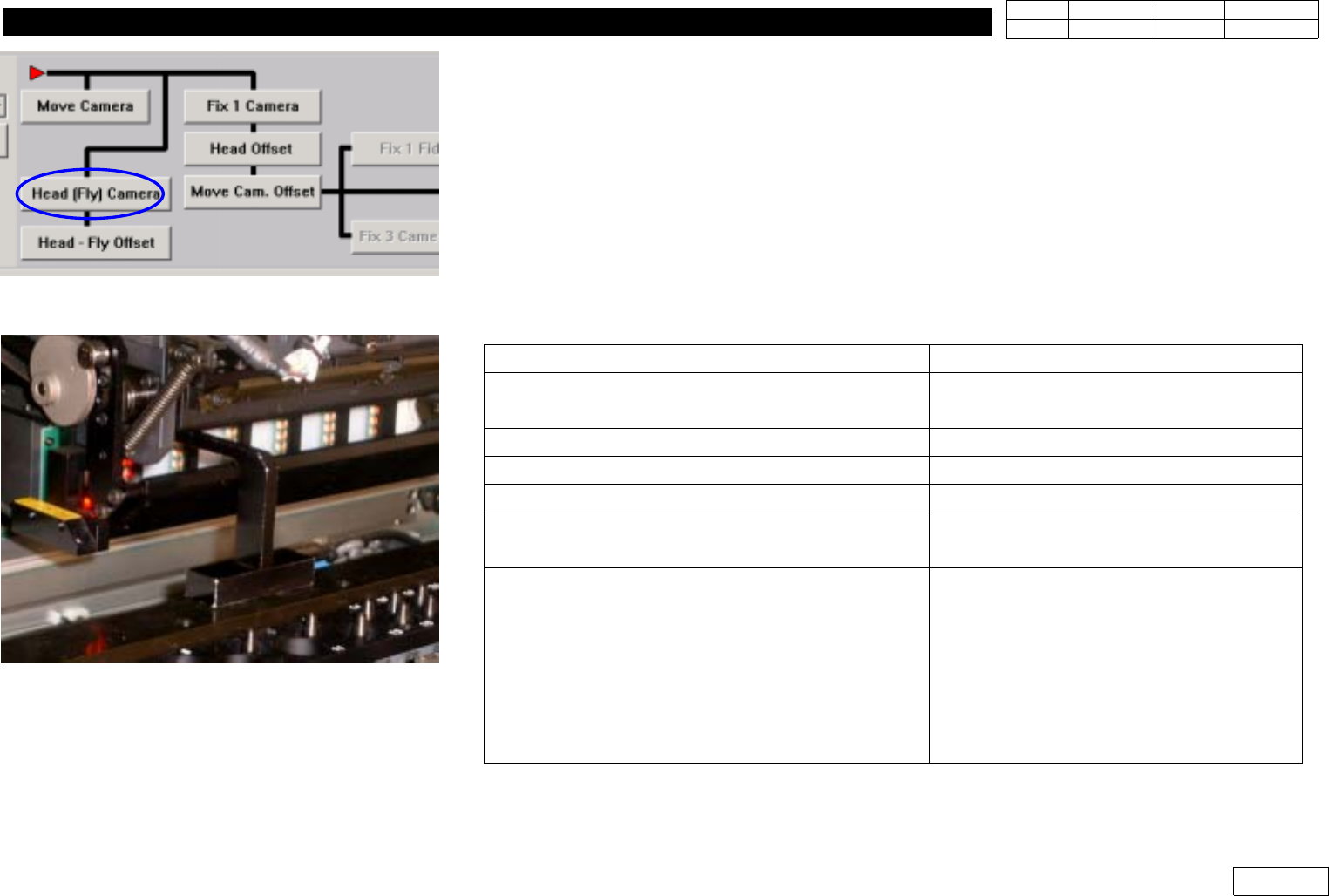
1] Menu : Select Sys. seup => Camera => Calibration =>Head(Fly) Camera (Ref. Fig 1.2.1)
2) Remove Mirror Cover of Head Module
3) Remove Nozzle of Head ('Put all Nozzle')
4) Click 'Head(Fly) Camera' to Display Messages Below. Proceed in Order
Message
Procedure
First, we must put all nozzles from heads
manually To moving down Z Axis,click[hear]
Check if There is No Nozzle and Click
'Next' =>(Caution) Mirror Moves to 45'
'Z axis moving down Please wait for a minute'
Stand by Until Next Message
'Next, Mirror will close. To close, click [Next]'
Click 'Next'
'Moving now,Please wait for a moment'
Stand by Until Next Message
'Setting the fly camera calibration tool on
conveyor finished, then click[Next] for next step'
Install Calibration Tool as Fig.1.2.2 and
Click 'Next'
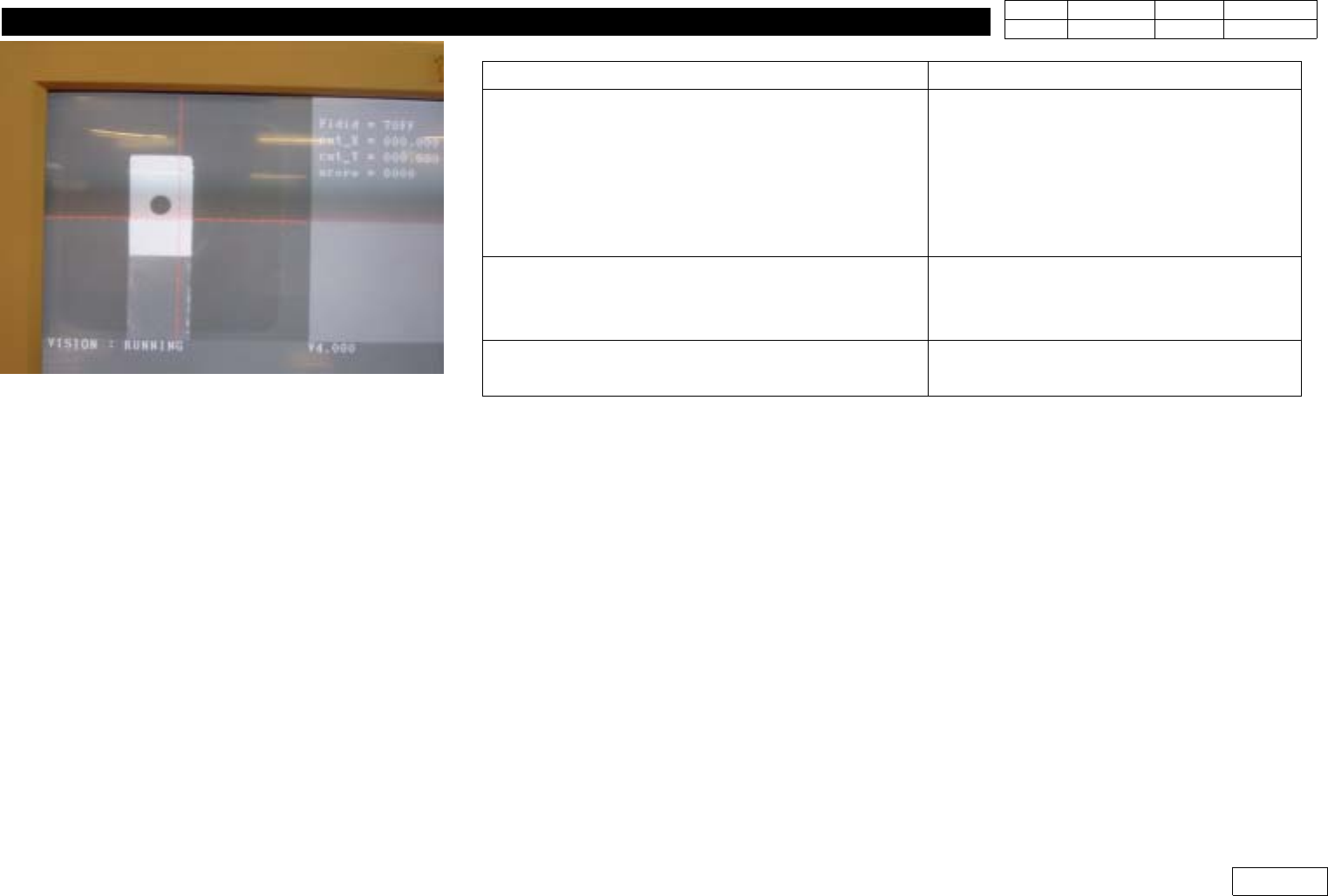
'Adjust between vision screen center to mark
center by jogbox [head 1 Camera]
To calibratation, Click [Next]
Using Jogbox, Make the Center of Head1
Camera(Center of Vision Monitor) Coincide
with the Center of Calibration Tool and
Click 'Next' (Ref. Fig.1-2-3) => Camera of
Head1 is Calibrated and the Output
(Previous and Present Value) is Printed
Fig.1-2-1 Head(Fly) Camera Calibration.
Fig.1-2-2 Install calibration tool on the C/V
1. Head Module
Ver. Date CP45
CP45NEO
00 2004/11 O O
1-1
Message
Process
'Adjust between vision screen center to mark
center by jogbox [head 2 Camera]
To calibratation, Click [Next]
(1) Using Jogbox, Make the Center of
Head2 Camera(Center of Vision Monitor)
Coincide with the Center of Calibration Tool
and Click 'Next' (Ref. Fig.1-2-3) => Camera
of Head2 is Calibrated
2)ProceedtoHead6theSameWay
'Removing the tool on the conveyor Finished,
then click [Next]'
Be Sure to Remove Calibration Tool before
Clicking Next
'Fly head camera calibrationis finished'
Calibration is Finished
=> Press 'Update' to Apply the Result
Fig.1-2-3 Align the center between camera
and calibration tool
1. Head Module
Ver. Date CP45
CP45NEO
00 2004/11 O O
1-1
1-3.Head-Fly Offset
*Tools
a) Calibration Tool ( in ANC 1st pocket)
*Parts
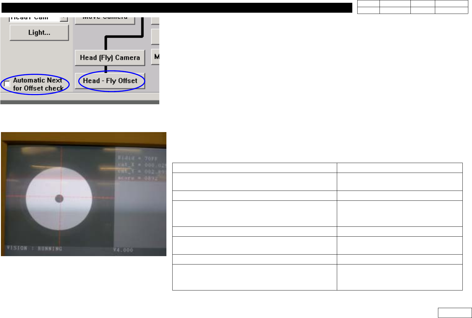
1] Menu : Select Sys. seup => Camera => Calibration => Head-Fly Offset (Ref. Fig1-3-1)
(Measure and Correct Offset btw. the Center of Flying Vision Camera and the Center of
Head(Nozzle End))
2) If There are Nozzles in Head, Remove All (Manually or Use Put All Nozzle in Lower Tool Menu)
3) In Case the Location of ANC Pocket is Exact
=> Be Able to Use It by Clicking 'Automatic Next for Offset Check' and Offset is Automatically
Measured
4) In Case the Location of ANC Pocket is Not Certain
=> Install Calibration Tool Each Time Manually w/o Selecting 'Automatic Next for Offset Check' and
Proceed Measurement (as Following Message)
Fig.1-3-1 Head-Fly Camera Offset manu
Message Process
'First, we must put all nozzles from head manually
To moving down Z axis, Click [Next]'
Click Next
=>MovetoHead1Home
'Z-axis moving down,Please wait for a moment'
Stand by Until Next Message
'Next, Attach the calibration tool to head 1.
Click[Next] for moving down head
After moving, Attach the tool to head manually.
Click Next => Head1 Goes Down
=>Insert Calibration Tool in Head1
'Z-axis moving down,Please wait for a moment'
Stand by Until Next Message
'Uptoalignheightandmirrorclose
To move, click [Next]
Click Next
=> Mirror Moves to Sensing Position
'Moving now, Please wait for a moment'
Stand by Until Next Message
'Calibration is prepared. To calibration,click[Next]
Click Next
=> Perform Calibration(Check Vision
Monitor)
Fig.1-3-2 Head-Fly Camera Offset Calibration