LS-Ge.pdf - 第12页
When set to light in FREE position When set to light in PUSHed (operating) position (PUSH) Series connection PC connection possible FREE position PUSHed (operating) position FREE position PUSHed (operating) position Up t…
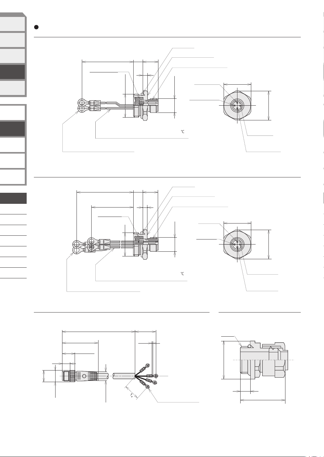
Sealed connector with
LS-PA52 2-lead cable
Sealed connector with LS-PA54 4-lead cable
PA5-4BX03HK4-E connector cable PA1-A10PF sealed connector
(unit: mm)
Connector dimensions
Blue, Black
40
83
+10
0
Brown, white
M12
12 dia.
14 dia.
9
15.5
44
320
+32
0
(1)
38
8
26
External
thread
M12×1
24
8
4
14
45
+5
0
85
+10
0
G1/2
O ring: P18
Housing material: Brass
Connector material : Nylon resin
8
4
1485
+10
0
G1/2
M12×1
26.4 dia.
24
Crimp- type terminal lug:
J.S.T MFG Co., Ltd. V0.5-4 or equivalent
Epoxy resin filled
White, black
White, black
Red, green
O ring: P18
Housing material: Brass
Connector material : Nylon resin
Epoxy resin filled
Crimp- type terminal lug:
J.S.T MFG Co., Ltd. V0.5-4 or equivalent
Pin No.1
Lead color: Red
Pin No.4
Lead color: White
26.4 dia.
Crimp- type terminal lug:
J.S.T MFG Co., Ltd.
V1.25-M4 or equivalent
Pin No.2
Blank terminal
Pin No.3
Lead color: Black
Pin No.1
Blank terminal
Pin No.4
Lead color: White
Pin No.
Lead color:
Green
Pin No.3
Lead color:
Black
Lead: Heat - resistant vinyl lead UL1007 (300V 80 )
AWG22 (17/0.16) twisted lead
Lead: Heat - resistant vinyl lead UL1007 (300V 80 )
AWG22 (17/0.16) twisted lead
D-033
LIMIT SWITCHES
WITH POSITIVE
OPENING MECHANISM
GENERAL PURPOSE
LIMIT SWITCHES
TECHNICAL GUIDE
FOR
LIMIT SWITCHES
EXPLOSION-PROOF
SWITCHES
TECHNICAL GUIDE FOR
EXPLOSION-PROOF
SWITCHES
SPATTER-GUARDED
LS
1LS-J7
1LS-J8
VCL-
1LS-J401
SL1-
SL1-C
PHOTOELECTRIC
SENSORS &
SWITCHES
MEASUREMENT
SENSORS
PROXIMITY
SWITCHES
LIMIT
SWITCHES
SAFETY
KEY SWITCHES
STANDARD
LS
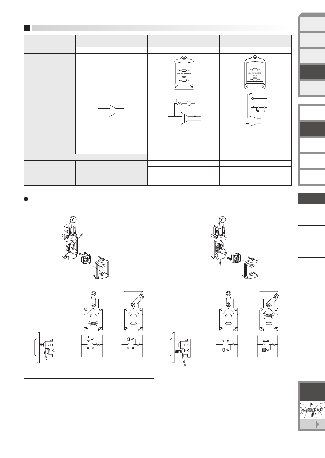
When set to light in FREE position
When set to light in PUSHed (operating) position (PUSH)
Series connection PC connection possible
FREE position
PUSHed (operating) position
FREE position
PUSHed (operating) position
Up to six switches can be connected in series when the power is
100V. Programmable controllers can also be connected in series.
The brightness of the LED lamp is fixed regardless of the power, as
light is generated by a built-in fixed current diode.
(Note that neon lamp type "E" Series switches cannot be
connected in series at 100V.)
The leakage current when the limit switch is not operating is 0.6 mA
maximum. The PC will not malfunction due to dim lighting of the
LED. Moreover, a fixed-current diode is built in to ensure fixed LED
brightness regardless of the voltage.
Option Without indicator lamp
Catalog listing
—
Circuit diagrams
Notes
—
LS-29PA1 LS-29PAEC
Operating voltage
Thermal current
Resistance
100 kΩ
Lamp cover
front side
Lamp cover catalog listing (replacement part)
Specifications
With 100/200 Vac
neon lamp
With 12 to 125V
LED lamp for AC or DC
100 to 200 Vac
100 Vac 200 Vac
Approx. 0.5 mA Approx. 1.5 mA
12 to 125V, AC or DC
12 to 125V
Max. 0.6 mA
33 kΩ
INDICATOR LAMP
Notes To ensure lighting of the
neon lamp, use 75 Vac min.
Notes The voltage indicator lamp
(red LED) is 12 to 125V.
The indicator lamp operates
on either AC or DC power.
Connection/operation of lamp cover
N.O.contact
N.C.contact
LS-J LS-JE LS-JEC
N.O.3
N.C.1
N.O.4
N.C.2
N.O.3
N.C.2
N.O.4
N.C.1
Ne
100 kΩ
N.O.3
N.C.2
N.O.4
N.C.1
D-034
LIMIT SWITCHES
WITH POSITIVE
OPENING MECHANISM
GENERAL PURPOSE
LIMIT SWITCHES
TECHNICAL GUIDE
FOR
LIMIT SWITCHES
EXPLOSION-PROOF
SWITCHES
TECHNICAL GUIDE FOR
EXPLOSION-PROOF
SWITCHES
F-001
See page
Connector
with cable
SPATTER-GUARDED
LS
1LS-J7
1LS-J8
VCL-
1LS-J401
SL1-
SL1-C
PHOTOELECTRIC
SENSORS &
SWITCHES
MEASUREMENT
SENSORS
PROXIMITY
SWITCHES
LIMIT
SWITCHES
SAFETY
KEY SWITCHES
STANDARD
LS
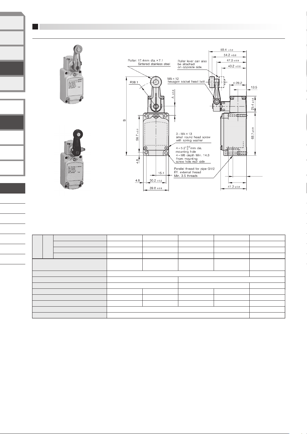
(unit: mm)
—
—
13.4 8.9
2.2 0.98 0.98
20
5 10
20 30
30 30 55
62
60
12 3 12 5
15
125
REF
127.5
REF
Standard type (-10 to +70˚C)
Heat-resistant type (-10 to +120˚C)
Cold-resistant type (-40 to +70˚C)
Corrosion-resistant type (-10 to +70˚C)
*1
1LS1-J
1LS1-JH
1LS1-JL
1LS1-JM
1LS19-J
1LS19-JH
1LS19-JL
1LS19-JM
1LS-J500
1LS-J500H
1LS-J500L
1LS-J500M
1LS-J550
1LS-J550H
1LS-J550L
1LS-J550M
1LS-J50
1LS-J50H
Standard travel,
standard characteristics
Standard travel,
high sensitivity
High overtravel,
standard characteristics
High overtravel,
high sensitivity
High overtravel,
90˚ T.T.
17.2±0.8
14.7±0.8
Note *1. Exactly the same as 1LS1-J except for different lever shape. For details on the lever shape, see 6PA78-JM (page D-043, 044).
—
Catalog
listing
Operating characteristics
UL/CSA/GB
O.F. (Max. N)
R.F. (Min. N)
P.T. (Max. ˚ )
O.T. (Min. ˚ )
M.D. (Max. ˚ )
Section A dimensions
Section B dimensions
Roller lever type
Standard type
Heat-resistant type
Cold-resistant type
Corrosion-resistant
type
APPEARANCE, OPERATING CHARACTERISTICS AND EXTERNAL DIMENSIONS
2-circuit
double break
+
2
–1
+
2
0
*
Dimensional tolerance is ±0.4 unless otherwise specified.
21.6 ±0.8
28.7
D-035
LIMIT SWITCHES
WITH POSITIVE
OPENING MECHANISM
GENERAL PURPOSE
LIMIT SWITCHES
TECHNICAL GUIDE
FOR
LIMIT SWITCHES
EXPLOSION-PROOF
SWITCHES
TECHNICAL GUIDE FOR
EXPLOSION-PROOF
SWITCHES
SPATTER-GUARDED
LS
1LS-J7
1LS-J8
VCL-
1LS-J401
SL1-
SL1-C
PHOTOELECTRIC
SENSORS &
SWITCHES
MEASUREMENT
SENSORS
PROXIMITY
SWITCHES
LIMIT
SWITCHES
SAFETY
KEY SWITCHES
STANDARD
LS