LS-Ge.pdf - 第27页
The minimum bend radius (R) of the cable is 80 mm. Allow sufficient cable for bends. When removing connectors to replace the switch or cable, wipe the connector and the surrounding area thoroughly to remove any water. Af…
If the screw of the mating part is made of resin, the threads can
easily be damaged when the connector is first tightened. When
assembling the connector, align the center of the cores, push in as
far as possible, and then turn to tighten.
Be sure to tighten fully by hand. The recommended tightening
torque is 0.4 to 0.6 N
·
m. Use of a tightening tool may damage the
connector. If the connector is not tightened firmly, IP67 protection
may be lost, or the connector may come loose.
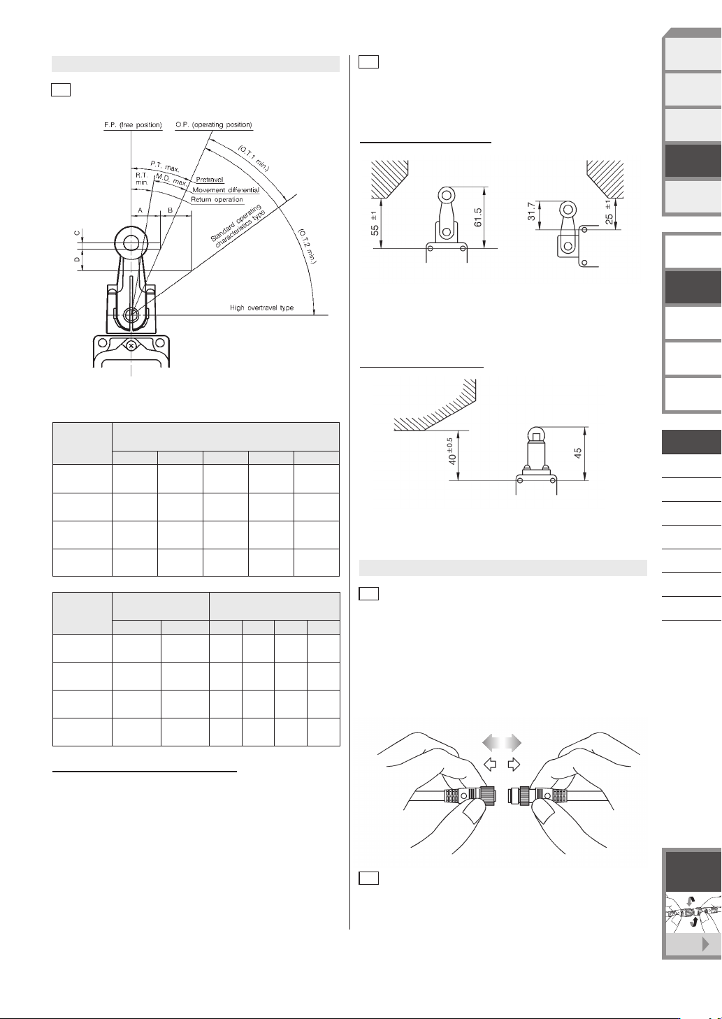
Roller lever type
For roller lever type switches, we recommend setting the distance from
the switch mounting hole to the actuating element as shown below.
5.1
Roller lever type
6.1
Tightening the fixing cap ring and outside screw lock ring
Before inserting or removing connectors, be sure to the turn the
power OFF. When removing, hold the connector itself--do not pull
by the cable.
6.2
Inserting and removing connectors
5.2
Height from switch mounting hole to actuating element
Example: 1LS1-J (unit: mm)
Roller plunger type
For roller plunger type switches, we recommend setting the distance
from the switch mounting hole to the actuating element as shown
below.
Example: 5LS1-J (unit: mm)
Key to the abbreviations used in the above tables:
P.T. : Pretravel
O.T. 1 : Overtravel (standard switch)
O.T. 2 : Overtravel (high overtravel switch)
R.T. : Return operation
M.D. : Movement differential
O.F. : Operating force
R.F. : Release force
Symbol
Operating angle (˚ )
Model
P.T. O.T.1 O.T.2 R.T. M.D.
1LS1-J 20
1LS19-J 5
+2
0
1LS-J500
20
1LS-J550
+2
-1
10
30
30
—
—
—
—
55
62
1.5
5
5
5
12
3
12
5
Symbol
Operating force (N) A,B,C,D distance (mm)
Model
C
1LS1-J
1LS19-J
1LS-J500
1LS-J550
O.F.
13.4
13.4
8.9
8.9
R.F.
2.2
2.2
0.98
0.98
A
13.0
3.3
13.0
6.6
B
16.1
18.5
23.8
29.6
2.3
0.1
2.3
0.6
D
11.3
6.7
25.9
25.7
6.
Handling the connector and preleaded connector
5.
How to set the actuating element
D-048
LIMIT SWITCHES
WITH POSITIVE
OPENING MECHANISM
GENERAL PURPOSE
LIMIT SWITCHES
TECHNICAL GUIDE
FOR
LIMIT SWITCHES
EXPLOSION-PROOF
SWITCHES
TECHNICAL GUIDE FOR
EXPLOSION-PROOF
SWITCHES
F-001
See page
Connector
with cable
SPATTER-GUARDED
LS
1LS-J7
1LS-J8
VCL-
1LS-J401
SL1-
SL1-C
PHOTOELECTRIC
SENSORS &
SWITCHES
MEASUREMENT
SENSORS
PROXIMITY
SWITCHES
LIMIT
SWITCHES
SAFETY
KEY SWITCHES
STANDARD
LS
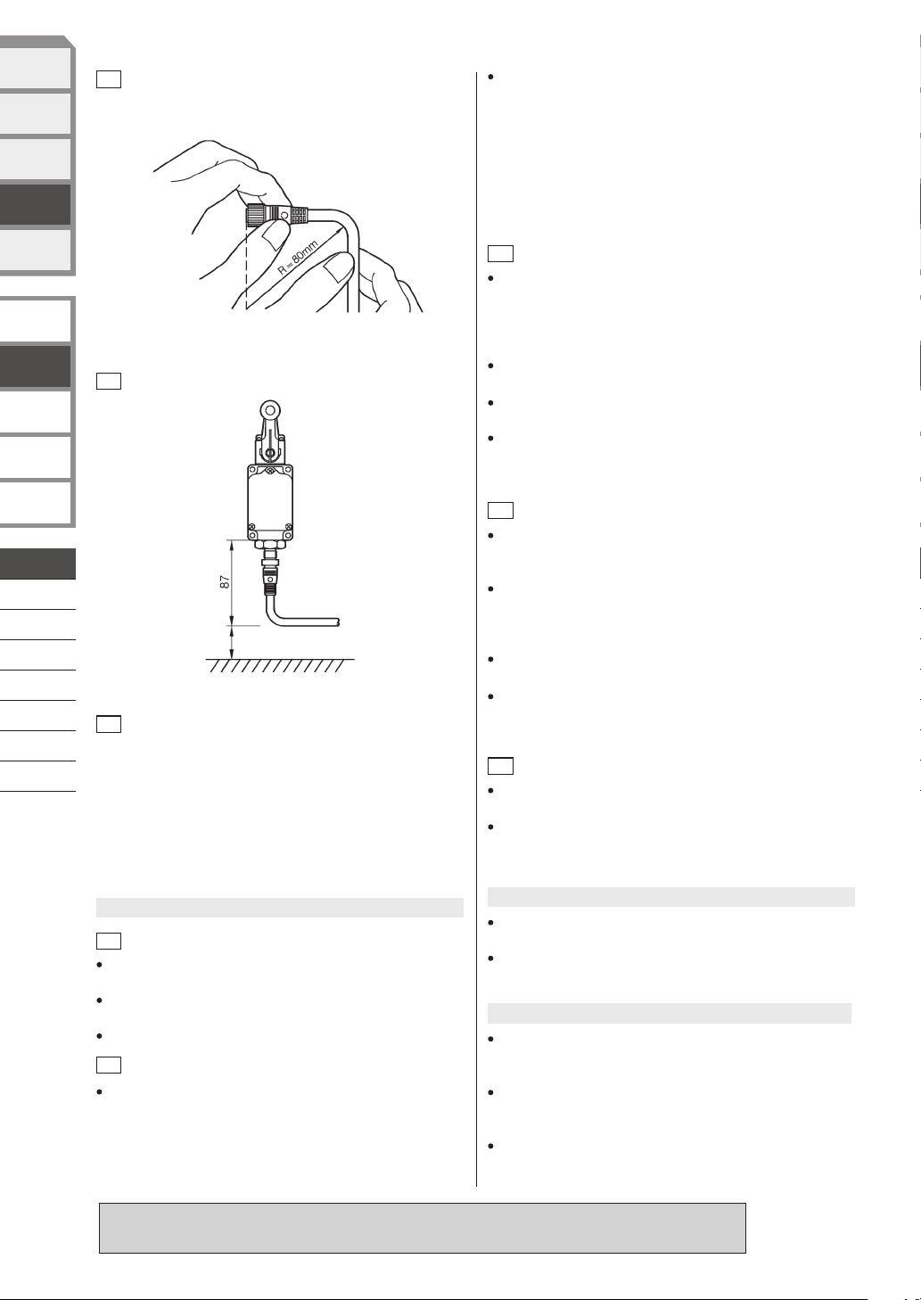
The minimum bend radius (R) of the cable is 80 mm. Allow sufficient
cable for bends.
When removing connectors to replace the switch or cable, wipe the
connector and the surrounding area thoroughly to remove any water.
After removing the connector, do not allow it to be immersed in
chemicals or powder, or to be dropped. If the connector is immersed in
a fluid, allow it to fully dry before connecting again. If the connector is
dropped in powder, wipe it off completely before connecting again.
Failure to observe these precautions may result in a short circuit or a
failed connection.
6.3
Cautions when bending cables
6.4
Installation of connector type switches
6.5
Cautions when replacing connectors
7.3
Attaching switches
When the screws in the head or covers are loosened to change the
operating direction of the switch, or the relationship between switch
operation and the indicator lamp (lamp ON during switch standby /
during switch operation), tighten the screws to the recommended
tightening torque to ensure a good seal.
Tighten each of the parts on the limit switch according to the
appropriate tightening torques listed in the performance tables.
Overtightening damages screws and other parts. On the other hand,
insufficient tightening of screws lowers the effectiveness of the seal
and reduces various performance characteristics.
Do not leave or use covers and conduit parts open. Water, dirt, or dust
may enter, which causing malfunction.
Prevent impact to the lever body and head. Failure to do so might
deform the actuator or cause defective switch return.
Do not use silicone rubber electrical lead insulation, silicone adhesive
or grease containing silicone. Doing so might result in defective
electrical conductivity.
Do not perform wiring with the power ON. Doing so might cause
electric shock, or the machine may start unexpectedly, causing an
accident.
Use crimp-type terminal lugs with covered insulation for electrical leads
to prevent contact with covers and housings. If a crimp-type terminal
lug contacts a cover, the cover may no longer shut or a ground fault
may occur.
Use sealed connectors (PA1 Series, etc. sold separately) or flexible
tubing (PA3 Series) with IP67 or equivalent seal for conduits.
Firmly tighten covers and conduits. If covers and conduits are not
sufficiently tightened, the seal will be impaired and switch performance
will no longer be assured.
Do not apply excessive force (5 times O.F.) to the actuator beyond the
total travel position. Doing so might damage the switch.
Keep overtravel between 1/3 to 2/3 of the rated value. Small overtravel
might cause the contacts to rattle due to vibration and impact, or may
result in defective contact.
Do not use the product in an environment where the cover may
directly come into contact with any strong volatile solvent.
Do not use the switch in an environment where strong acid or alkali is
directly splashed onto it.
Recommended tightening torque
Cover: 1.3 to 1.7 N
·
m (M4 screw)
Head: 0.8 to 1.2 N
·
m (M3.5 screw)
7.4
Wiring
7.5
Adjusting switches
(unit: mm)
Approx.15
(insertion/removal space)
8.
Environment
Do not apply a lubricant to the sliding part of the actuator or any other
component. Application of an inappropriate lubricant may degrade
sliding performance or impair the protective structure.
Remove any foreign substances adhering to the sliding part. Dust or
any other foreign substance attached to the sliding part may cause a
malfunction.
Check the actual load.
To increase reliability, confirm that the switch has no problems in
actual use before using the switch.
Before use, thoroughly read the “Precautions for use” and “Precautions for handling” in the Technical Guide
on pages D-101 to D -112 as well as the instruction manual and product specification for this switch.
IP67 protection does not assure complete waterproofing. Switch
should not be in constant contact with water.
Avoid use where external force is applied at all times on the connecting
section of the connector.
Do not use the body as a step or place heavy objects on top of it.
When general-purpose limit switches are used in locations subject to
splashing by water, oil, dirt and dust, or chips, water or oil sometimes
enters the switch from the conduit due to capillary action. For this
reason, be sure to use a sealed connector compatible with the cable.
7.1
Protective structure
7.2
Ensuring a good seal
7.
Other
9.
Other cautions
D-049
LIMIT SWITCHES
WITH POSITIVE
OPENING MECHANISM
GENERAL PURPOSE
LIMIT SWITCHES
TECHNICAL GUIDE
FOR
LIMIT SWITCHES
EXPLOSION-PROOF
SWITCHES
TECHNICAL GUIDE FOR
EXPLOSION-PROOF
SWITCHES
SPATTER-GUARDED
LS
1LS-J7
1LS-J8
VCL-
1LS-J401
SL1-
SL1-C
PHOTOELECTRIC
SENSORS &
SWITCHES
MEASUREMENT
SENSORS
PROXIMITY
SWITCHES
LIMIT
SWITCHES
SAFETY
KEY SWITCHES
STANDARD
LS

CP-GC1003E Vol.2
[Notice] Specifications are subject to change without notice.
No part of this publication may be reproduced or duplicated
without the prior written permission of Azbil Corporation.
Yamatake Corporation changed its name to Azbil Corporation on April 1, 2012.
1-12-2 Kawana, Fujisawa
Kanagawa 251-8522 Japan
URL: https://www.azbil.com
1st Edition : Jan. 2018
Other product names, model numbers and company names may be trademarks of the respective company.
Please read “Terms and Conditions” from the following URL before
ordering and use.
https://www.azbil.com/products/factory/order.html
(15)