LS-Ge.pdf - 第25页
WHEN USING LS SERIES LIMIT SWITCHES The operating head can be set to four positions. To set to the desired position, remove the four head tightening screws and rotate the head 90˚ to one of the four different positions. …
Lamp cover
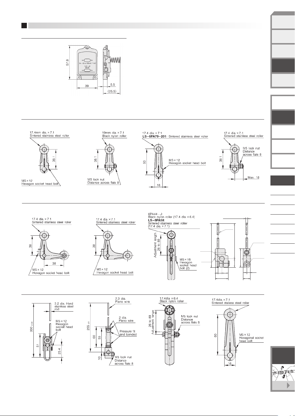
Auxiliary actuators
AUXILIARY PART DIMENSIONS
(unit: mm)
LS-29PA1, LS-9PAW
LS-29PAEC, LS-9PAWC
LS-6PA79-201
6PA-J148, 6PA78-J
6PA78-JW
6PA78-JM
6PA-J45
6PA-J45W
6PA63-J 6PA-J546PA-J40 PA-J11
6PA80-J 6PA74-J
6PA44-J
LS-6PA58
6PA43-J
6PA-J176
7.3 dia.
hole
+0.1
0
Lever
body
Rod
6.4
13.8
Max. 142
Max. 141
30
10
11. 8
5.9
20.8
M8×8
Hexagon
socket
set screw
M5×8
Hexagon
socket
head bolt
3.2 dia. ±0.1
Stainless steel
D-046
LIMIT SWITCHES
WITH POSITIVE
OPENING MECHANISM
GENERAL PURPOSE
LIMIT SWITCHES
TECHNICAL GUIDE
FOR
LIMIT SWITCHES
EXPLOSION-PROOF
SWITCHES
TECHNICAL GUIDE FOR
EXPLOSION-PROOF
SWITCHES
F-001
See page
Connector
with cable
SPATTER-GUARDED
LS
1LS-J7
1LS-J8
VCL-
1LS-J401
SL1-
SL1-C
PHOTOELECTRIC
SENSORS &
SWITCHES
MEASUREMENT
SENSORS
PROXIMITY
SWITCHES
LIMIT
SWITCHES
SAFETY
KEY SWITCHES
STANDARD
LS
WHEN USING LS SERIES LIMIT SWITCHES
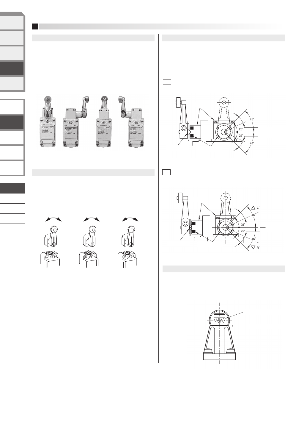
The operating head can be set to four positions. To set to the
desired position, remove the four head tightening screws and rotate
the head 90˚ to one of the four different positions. When changing
the direction of the operating head, change the direction of the
internal plunger at the same time (excluding
1LS-J500, 1LS-J550
and
1LS-J50). The roller plunger can be set to one of two different
positions 90˚ apart.
1.
Changing the position of the operating head
The operation direction can be set to three sequences (excluding
1LS-J500
, 1LS-J550 and 1LS-J50). Lever type limit switches can
be set to operate electrically when moved either clockwise or
counterclockwise by changing the direction of the internal stepped
plunger.
2.
Changing the operating direction of roller lever type
3.
Indicating the operation set position on the roller lever type
The indentation on the roller plunger is for preventing excessive or
insufficient plunger operation. Determine the position of the
actuating element so that the indentation on the plunger fits into the
top surface of the bushing.
Excessive or insufficient pushing of the lever can be eliminated to
ensure stable prolonged use by setting so that the pointer that
rotates with the lever enters the head's protrusion zone. The
position of the protrusion zone varies with different model types,
such as standard , high sensitivity, and 90˚ T.T. types.
3.1
Standard type (1LS1-J, 1LS-J50Series)
3.2
High-sensitivity type (1LS19-J, 1LS-J55Series)
Operation Operation Operation Operation
Standby Standby
Setting Pointer
Protrusion zone
Head
Appropriate
range
Setting Pointer
Protrusion zone
Indent Oppropriate range
Top surface of bushing
Head
Appropriate
range
4.
Indicating the operation set position of roller plunger type
(
5LS1-J
)
D-047
LIMIT SWITCHES
WITH POSITIVE
OPENING MECHANISM
GENERAL PURPOSE
LIMIT SWITCHES
TECHNICAL GUIDE
FOR
LIMIT SWITCHES
EXPLOSION-PROOF
SWITCHES
TECHNICAL GUIDE FOR
EXPLOSION-PROOF
SWITCHES
SPATTER-GUARDED
LS
1LS-J7
1LS-J8
VCL-
1LS-J401
SL1-
SL1-C
PHOTOELECTRIC
SENSORS &
SWITCHES
MEASUREMENT
SENSORS
PROXIMITY
SWITCHES
LIMIT
SWITCHES
SAFETY
KEY SWITCHES
STANDARD
LS
If the screw of the mating part is made of resin, the threads can
easily be damaged when the connector is first tightened. When
assembling the connector, align the center of the cores, push in as
far as possible, and then turn to tighten.
Be sure to tighten fully by hand. The recommended tightening
torque is 0.4 to 0.6 N
·
m. Use of a tightening tool may damage the
connector. If the connector is not tightened firmly, IP67 protection
may be lost, or the connector may come loose.
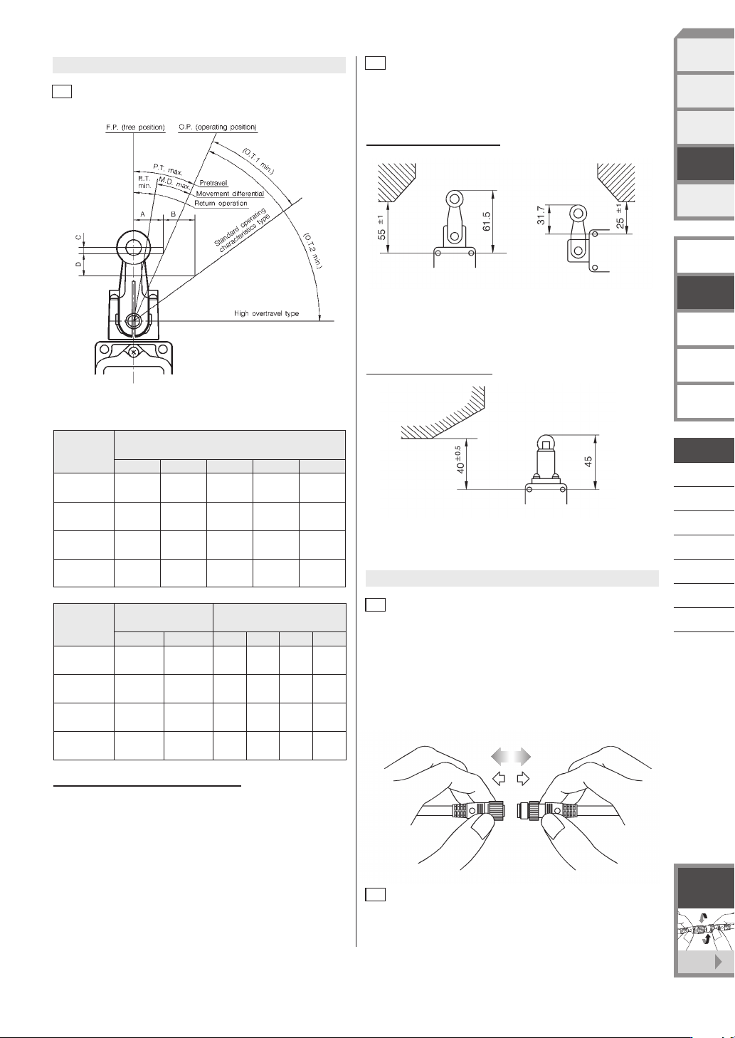
Roller lever type
For roller lever type switches, we recommend setting the distance from
the switch mounting hole to the actuating element as shown below.
5.1
Roller lever type
6.1
Tightening the fixing cap ring and outside screw lock ring
Before inserting or removing connectors, be sure to the turn the
power OFF. When removing, hold the connector itself--do not pull
by the cable.
6.2
Inserting and removing connectors
5.2
Height from switch mounting hole to actuating element
Example: 1LS1-J (unit: mm)
Roller plunger type
For roller plunger type switches, we recommend setting the distance
from the switch mounting hole to the actuating element as shown
below.
Example: 5LS1-J (unit: mm)
Key to the abbreviations used in the above tables:
P.T. : Pretravel
O.T. 1 : Overtravel (standard switch)
O.T. 2 : Overtravel (high overtravel switch)
R.T. : Return operation
M.D. : Movement differential
O.F. : Operating force
R.F. : Release force
Symbol
Operating angle (˚ )
Model
P.T. O.T.1 O.T.2 R.T. M.D.
1LS1-J 20
1LS19-J 5
+2
0
1LS-J500
20
1LS-J550
+2
-1
10
30
30
—
—
—
—
55
62
1.5
5
5
5
12
3
12
5
Symbol
Operating force (N) A,B,C,D distance (mm)
Model
C
1LS1-J
1LS19-J
1LS-J500
1LS-J550
O.F.
13.4
13.4
8.9
8.9
R.F.
2.2
2.2
0.98
0.98
A
13.0
3.3
13.0
6.6
B
16.1
18.5
23.8
29.6
2.3
0.1
2.3
0.6
D
11.3
6.7
25.9
25.7
6.
Handling the connector and preleaded connector
5.
How to set the actuating element
D-048
LIMIT SWITCHES
WITH POSITIVE
OPENING MECHANISM
GENERAL PURPOSE
LIMIT SWITCHES
TECHNICAL GUIDE
FOR
LIMIT SWITCHES
EXPLOSION-PROOF
SWITCHES
TECHNICAL GUIDE FOR
EXPLOSION-PROOF
SWITCHES
F-001
See page
Connector
with cable
SPATTER-GUARDED
LS
1LS-J7
1LS-J8
VCL-
1LS-J401
SL1-
SL1-C
PHOTOELECTRIC
SENSORS &
SWITCHES
MEASUREMENT
SENSORS
PROXIMITY
SWITCHES
LIMIT
SWITCHES
SAFETY
KEY SWITCHES
STANDARD
LS