A700000009046784.pdf - 第11页
11 Dispensin g head Dispensing head allows co nvenient dosing o f glue or solder pa ste from a 5 or 10 ml cartr idge. However, it is necessary to purchase a su itable dispenser. Description: Mounting o f the dispen sing …
10
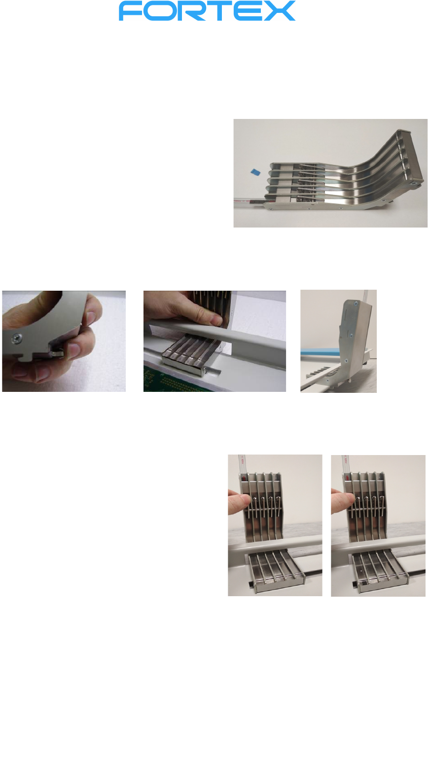
Stick feeder
The IC stick feeders allow the feeding of integrated circuits of various sizes directly from the sticks.
Insertion of IC sticks:
Remove the Feeder from the assembling desk, put it
backside on a flat horizontal surface. Take out the
safety latch from one end of the stick so that the
integrated circuits do not spill out. Slide this end
under the flexible holder as far as it goes. Repeat the
procedure for the required number of positions.
Holding teeth and the safety hook are used to fix the stick feeders to the assembling desk. Press the
safety hook as far as it goes. Insert the stick feeder (along with the sticks) through the rear opening and
insert both front and rear teeth under the metal plate. Release the safety hook to fix the feeder. Make
sure it is fixed properly.
Feeding of the ICs:
Press the pinch pad of the dosing mechanism in
the requested channel. One piece of the IC will slip
from the dosing mechanism to the picking position,
from where it can be easily picked up using a
respective needle or a suction cup.
If any of the sticks is emptied and you do not want
to remove the entire feeder, you can carefully
overfill integrated circuits from the full tube to the
empty one.
11
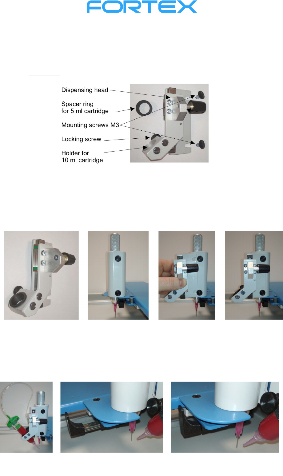
Dispensing head
Dispensing head allows convenient dosing of glue or solder paste from a 5 or 10 ml cartridge.
However, it is necessary to purchase a suitable dispenser.
Description:
Mounting of the dispensing head
Screw the M3 mounting screws into the holes on the assembling head. Insert the dispensing head as
far as it goes under the M3 mounting screws heads. Tighten the M3 mounting screws.
Insert the 10 ml cartridge into the holder so that the end of the dispensing nozzle is at the same height
as the end of the assembling needle. (For a 5 ml cartridge, also insert the spacer ring into the holder.)
Fix the cartridge position by a safety screw. Move the CCD camera to the front position so that the
dispensing nozzle is located in the center of the screen. Connect the hose into the dispenser (not
included).
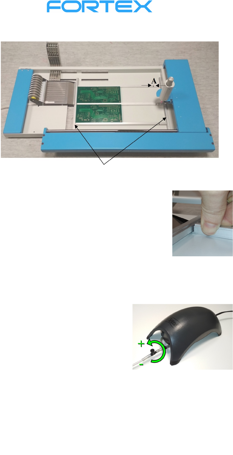
Placement of the PCB on the assembling desk
12
The PCB holders can be removed from assembling desk or relocated by pressing both ends together.
Side holders
Place the PCB holder on the surface of the assembling desk between the side
holders. First, slide the tab on one end of the holder all the way into the
groove at the bottom of the side holder. Lower the PCB holder and the
protrusion will snap into the groove of the second side holder.
Place the printed circuit board on the upper groove of the PCB holders. Set
the spacing between the PCB holders to the width of the PCB. If the size of
the PCB allows it, place more pieces on the work surface.
Vacuum pump
Caution! Use only the vacuum pump that is included
in the delivery (the pumps are specially adapted for use
with manipulators). Switch on the pump before starting the
manipulator and switch it off after manipulator has been
switched off. Set the intensity of the vacuum with the
control valve. The maximum vacuum is required to lift
large or heavy components, for small SMD it is
recommended to reduce the vacuum. The use of rubber
suction cups or a suitable needle diameter significantly
affects the vacuum required to lift the component.