DECAN_S1_Maintenance(Eng_Ver1.1)_Print.pdf - 第71页
Mon thly Inspe ction chapt er 5 Nex t Generation, Multi- Functi onal Placer DE CAN S1 M ain ten anc e Ha nd boo k 5-1 6 Cleaning and Lubricating X Frame LM Guide, Ball Screw Monthly Inspe ction Step 11. Fas ten th e bolt…
Monthly Inspection
chapter 5
Next Generation, Multi-Functional Placer
DECAN S1 Maintenance Handbook
5-15
Cleaning and Lubricating X Frame LM Guide, Ball Screw
Step 9.
Fasten the bolts fixing the cover in the order shown in
the following figure using a hex wrench (M3).
4
2
1
3
Caution
When assembling the grease scatter prevention cover, exercise great
care so that it will not be bent.
If the cover is bent, it cannot be used. Therefore, a new one must
be purchased.
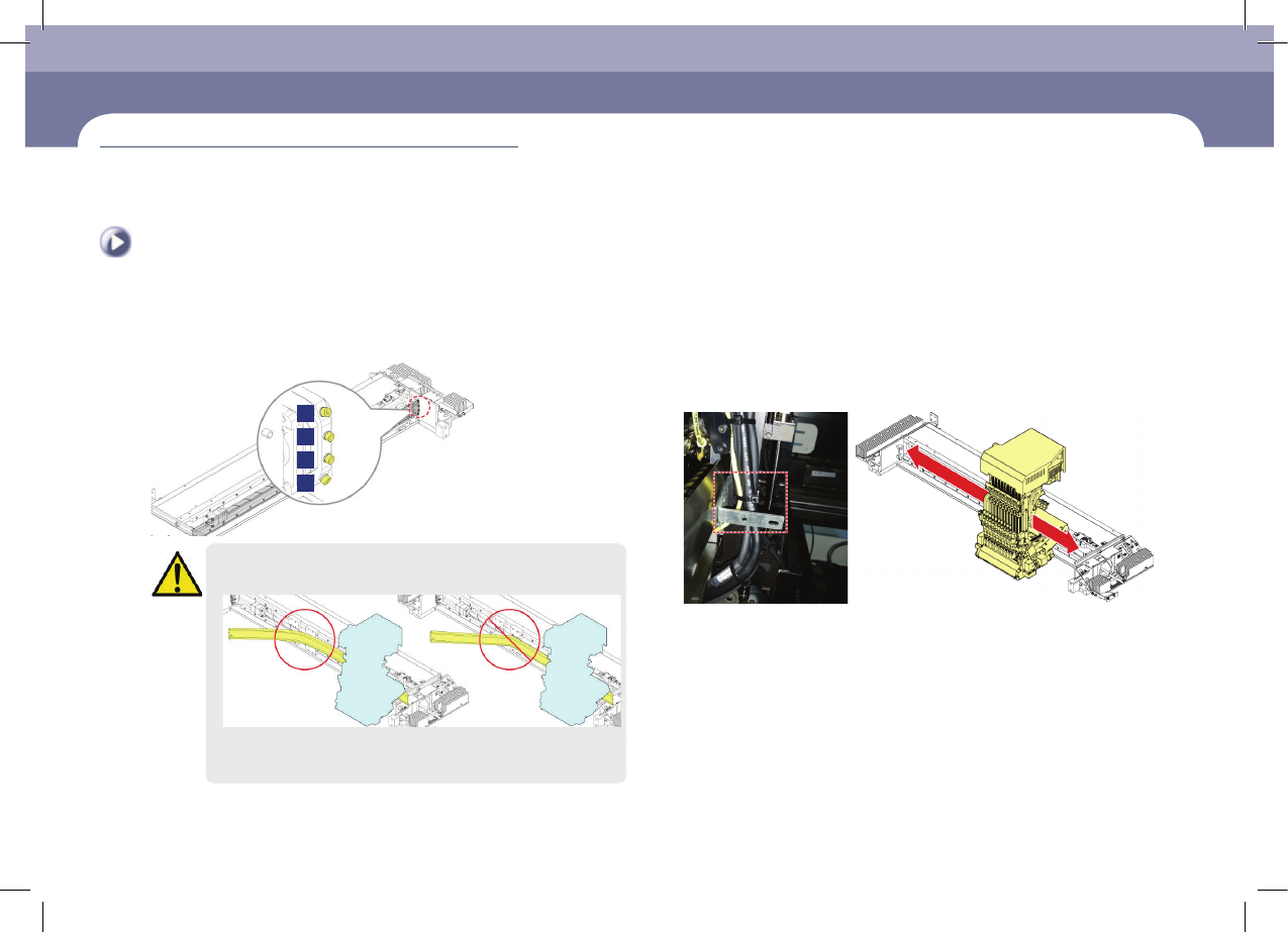
Step 10.
After inserting a steel plate with a thickness of 2.0mm
between the grease scatter prevention cover and head,
position the head at the center of the X-frame to check
whether the space between the cover and head is more
than 2.0mm.
Monthly Inspection
chapter 5
Next Generation, Multi-Functional Placer
DECAN S1 Maintenance Handbook
5-16
Cleaning and Lubricating X Frame LM Guide, Ball Screw
Monthly Inspection
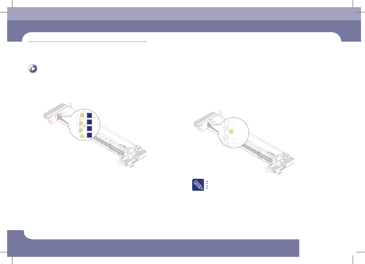
Step 11.
Fasten the bolts fixing the cover in the order shown in
the following figure using a hex wrench (M3).
4
2
1
3
Step 12.
Fasten the cover tension adjustment bolts using a hex
wrench (M4).
Fasten the tension adjustment bolts so that the block of the grease
scatter prevention cover and the spacer come into close contact.
Monthly Inspection
chapter 5
Next Generation, Multi-Functional Placer
DECAN S1 Maintenance Handbook
5-17
Cleaning and Lubricating X Frame LM Guide, Ball Screw
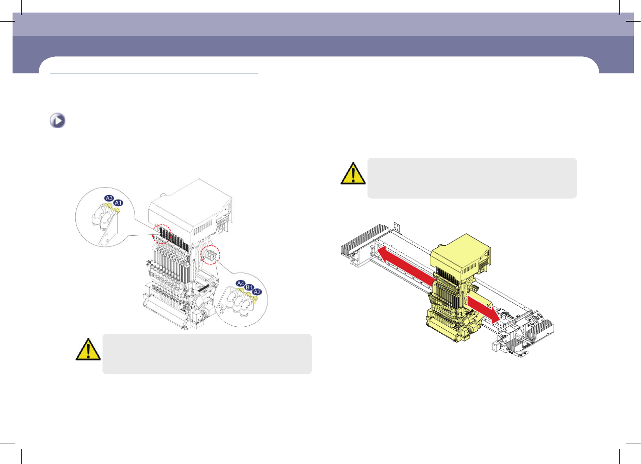
Step 13.
Inject the grease using a lubricator.
(A1 ~ A4: LM Guide, B1: Ball screw)
Caution
If the machine's operating environment is harsh, check its lubrication
status frequently.
Caution
The designated grease must be applied using the designated
lubricator in the designated manner. Other lubricating methods are
unacceptable.
Step 14.
Move the head assembly to the left and right three
times using a head assembly handle.
Step 15.
Release the emergency stop as described in "Releasing
'Emergency Stop' mode" on page 1-6 and perform the
operation again.