A10011-ASM-T53-EN-Spec-TX-micron-DMS.pdf - 第10页
10 Placement heads Nozzle changer Nozzle changer for the SIPLACE S peedSt ar (C&P20 M2) Nozzle changer for the S IPLACE Multi St ar (CPP M) Magazine for 20 nozzles of type 40xx Magazine for 9 nozzles of type 28xx Mag…

9
Placement heads
SIPLACE MultiStar (CPP M)
SIPLACE MultiStar (CPP M)
With component camera type 45
Component range
a
a) Please note that the placeable component range is also affected by the pad geometry, the customer-
specific standards, the component packaging tolerances and the component tolerances.
01005 to 15 mm x 15 mm
Component spec.
Max height
b
Max. height
c
Min. lead pitch
Min. lead width
Min. ball pitch
Min. ball diameter
Min. dimensions
Max. dimensions
Max. weight
b) CPP M head: in low installation position
c) CPP M head: in high installation position
6.0 mm
8.5 mm
250 µm / 120 µm
d
50 µm
140 µm
70 µm
0.11 mm x 0.11 mm
15 mm x 15 mm
4 g
d) Only available for components which are within the camera range of focus: ± 1.3 mm.
Set-down force 1.0 - 15 N
Nozzle types 20xx, 28xx
X/Y accuracy
e
With "accuracy class"
f
Without "accuracy class"
e) The benchmark and accuracy values are measured during the machine acceptance tests and corre-
spond to the conditions set out in the ASM scope of service and supply.
f) Setting in SIPLACE Pro Component Shape Editor
± 20 µm/3σ
± 25 µm/3σ
Angular accuracy ± 0.18° / 3σ
Illumination levels 5
10
Placement heads
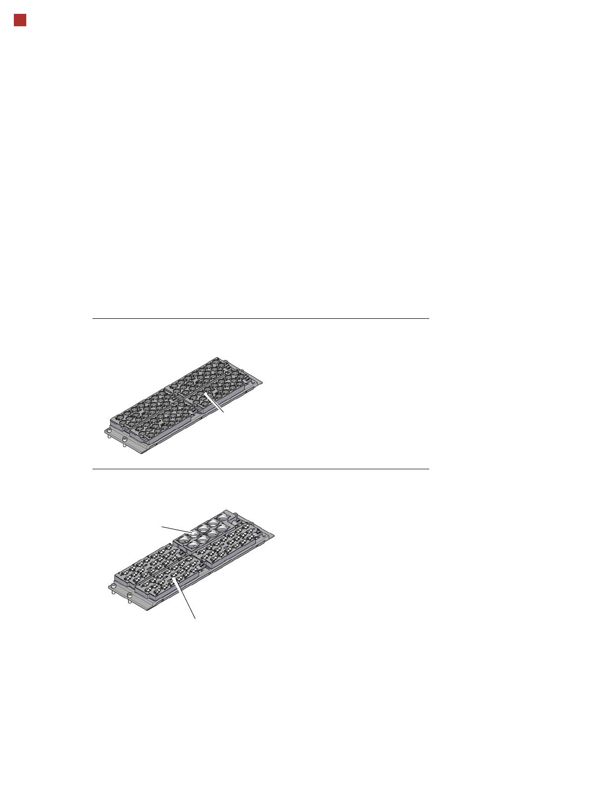
Nozzle changer
Nozzle changer for the SIPLACE SpeedStar (C&P20 M2)
Nozzle changer for the SIPLACE MultiStar (CPP M)
Magazine for 20 nozzles of type 40xx
Magazine for 9 nozzles of
type 28xx
Magazine for 20 nozzles of type 20xx
Description
Nozzle changers increase the flexibility of the placement heads when it comes to processing
different components. The nozzle configuration can be rapidly adjusted to changing place-
ment jobs. Precisely defined positions and perfect nozzle seat in the garage ensure minimum
radial eccentricity on the placement head.
The nozzle changers feature a monitoring circuit.This checks whether the nozzle magazines
are seated correctly on the mount.In addition, the nozzle changer recognizes whether the
magazines are for 40xx, 20xx or 28xx nozzles by the code.
11
Board conveyor
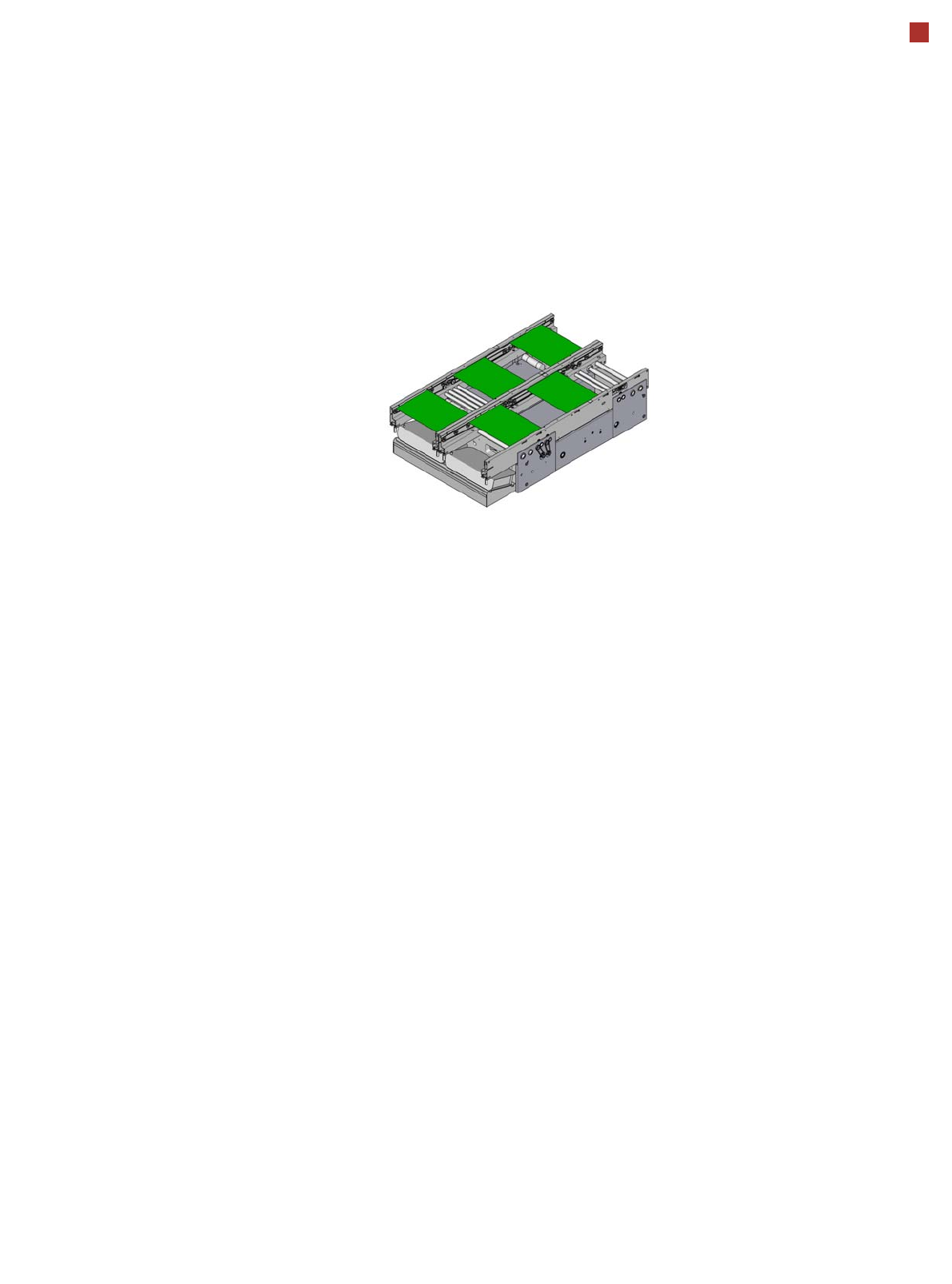
Flexible dual conveyor
Flexible dual conveyor
The flexible dual conveyor
has two conveyor tracks that
are electrically and mechani-
cally independent of one
another. The fixed conveyor
sides are both "outside" as a
default. As an option, the
fixed conveyor sides can be
selected as right/right or left/
left. The PCB dual conveyor
can also be operated as a
single conveyor, as an
option. In dual conveyor
mode, two boards are moved
into the placement machine
and placed either at the
same time (synchronous
mode) or alternatively (asyn-
chronous mode). This makes
it possible to process the top
and bottom sides of a board
in one line.
Synchronous mode
In synchronous mode, two
boards of the same size are
transported into the place-
ment position at the same
time. They are processed as
a common panel. When
using products with greatly
differing placement content,
common optimization
increases the performance of
the whole content on both
boards.
Asynchronous mode
In asynchronous mode, only
one board on a conveyor
lane is processed. At the
same time, another board on
the second conveyor lane is
moved into the placement
position. This saves the full
conveying time of one board,
thus considerably increasing
performance, particularly for
boards with a short cycle
time.
I-Placement
The SIPLACE line achieves
top placement performance
with the use of I-Placement.
In this mode, the two heads
work simultaneously and
populate the PCB on the cor-
responding conveyor side,
totally independently of one
another. Short distances fur-
ther increase the output.
Borrow Performance
By facilitating simultaneous
production of two boards with
different contents in one line,
Borrow Performance is the
ideal addition to I-Placement.
In placement machines with
Borrow Performance, both
heads place the same board
in alternation The board in
the other conveyor lane is
simply transported through
the system. This makes it
possible to achieve the same
cycle time for both boards,
despite the different place-
ment contents.
Convoy Mode
When processing boards
with lengths shorter than 175
mm, Convey Mode moves
more boards into the place-
ment area and input con-
veyor section. While one
board is being processed,
the second one waits directly
behind it. The transportation
time is therefore reduced sig-
nificantly, especially in I-
Placement mode.
Flexible dual conveyor