A10011-ASM-T53-EN-Spec-TX-micron-DMS.pdf - 第16页
16 Virtual Inkspot Handler (VIH) The virtual inks pot hand ler (VIH) allows you to scan in inkspots from an external system. This option can be use d for external systems to define which panels are to be produced and whi…
15
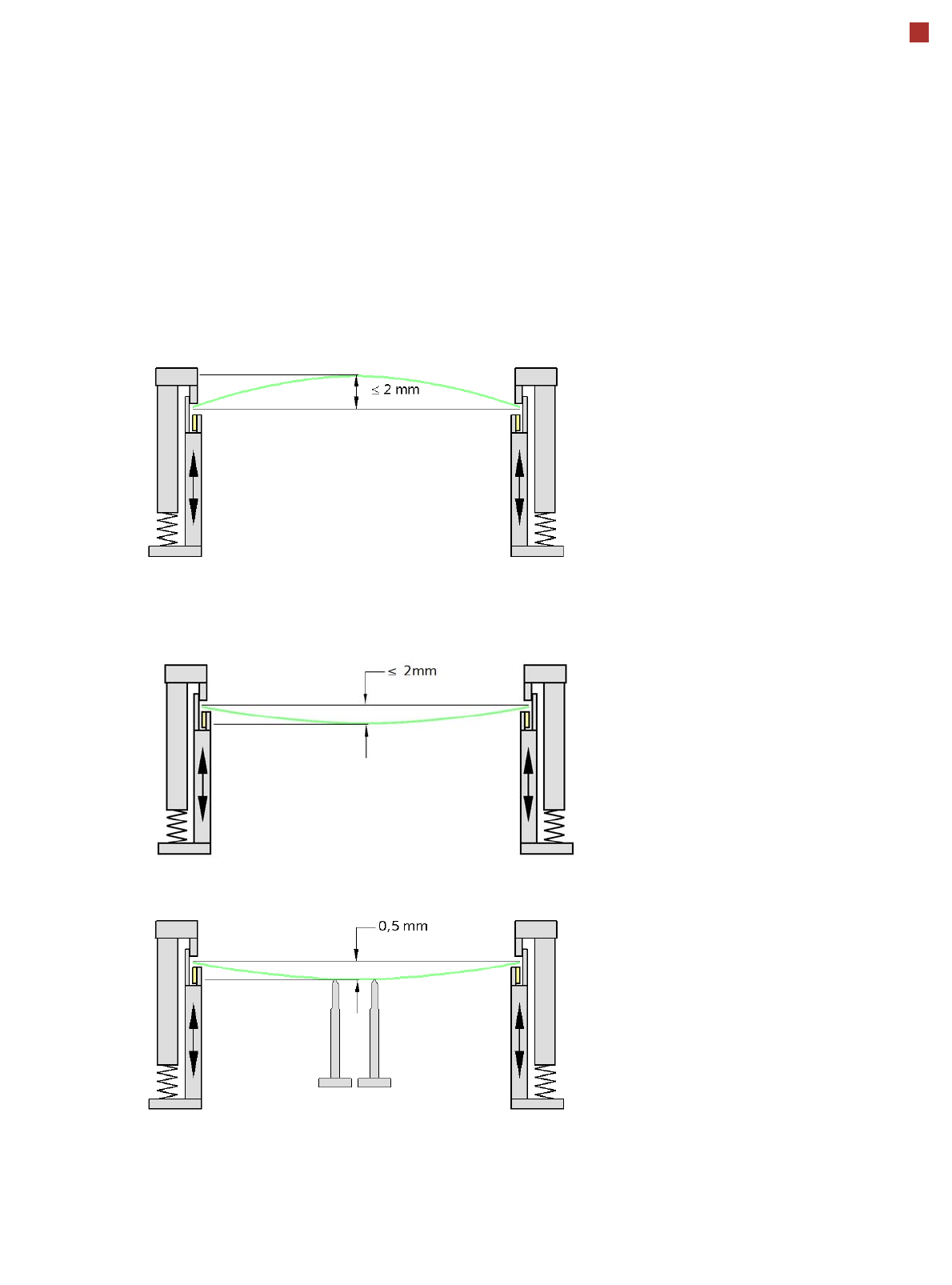
PCB warpage
PCB warpage during placement
To avoid impairing the placement quality and
speed, we recommend using a PCB support, so
that the PCB warpage downwards does not
exceed 0.5 mm.
PCB warpage up, max. 2 mm
PCB support
PCB warpage down, max. 2 mm
Changes in the surface position are automatically applied by the functions for learning the height.
16
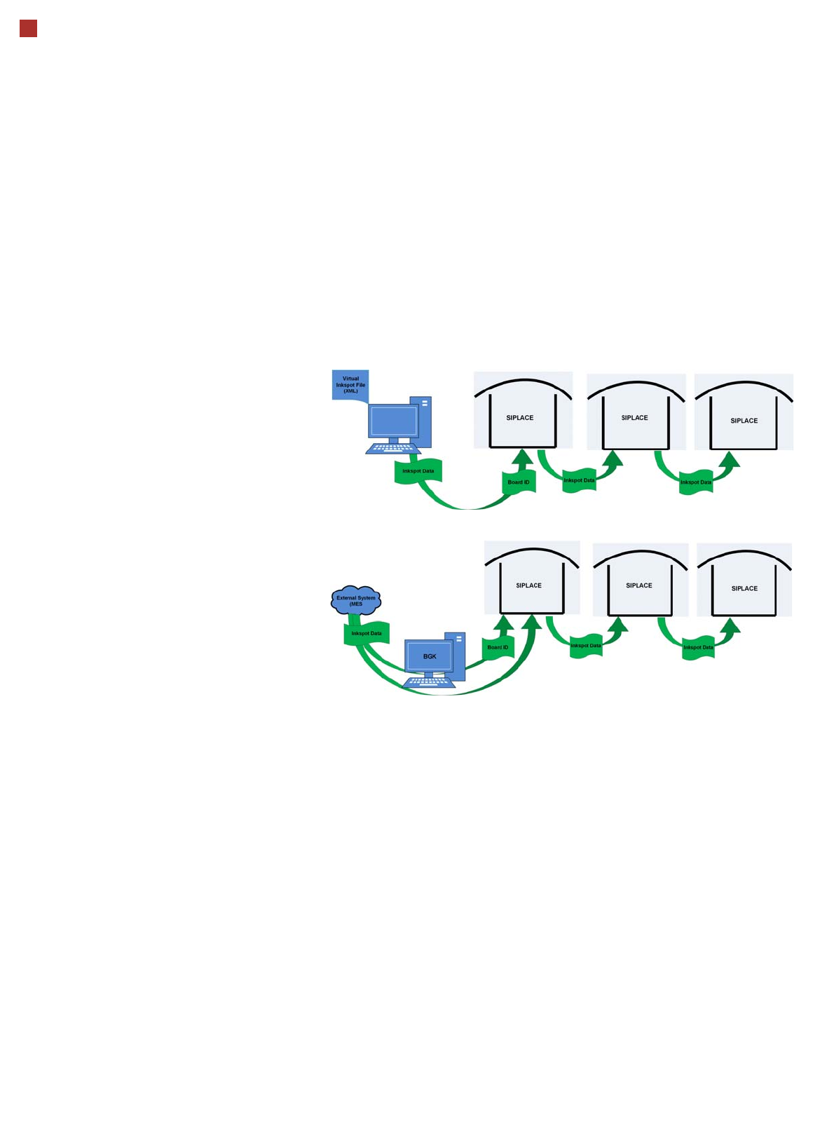
Virtual Inkspot Handler (VIH)
The virtual inkspot handler
(VIH) allows you to scan in
inkspots from an external
system.
This option can be used for
external systems to define
which panels are to be
produced and which to be
omitted. A panel is a specific
part of a printed circuit
board. This concept is much
more flexible than the
physical inkspot concept.
It can be integrated into the
ongoing production process,
if external systems
individually decide whether
each panel it is in a good or
bad state and whether
additional processing steps
are to be omitted or not.
The boards are typically
measured by the external
system and the information
about which panels are good
or bad is then available.
The use of this information
via VIH offers the benefit that
no physical inkspots need to
be read by the PCB camera.
This improves performance,
particularly for boards with a
large number of panels.
This option can also be used
if the panels do not have
room for a physical inkspot.
Workflow VIH with XML file
Workflow VIH with MES and BoardGateKeeper (BGK)
Process Data Interfaces (PDI)
The process data interface (PDI), which can be addressed via
the OIB interface, enables you to access not only the trace-
ability data of the components placed but also various process
parameters for the component placement. The PDI makes
over 40 process attributes per placement position available,
such as:
• Pickup (actual pick position, pickup location ID)
• Dipping (result, timestamp)
• Vision measuring (result plus camera ID)
• Placement (actual place position, ref. desig., vacuum val-
ues)
The data packages contain the data for each board and stop-
per position.
Each individual data package contains a maximum of 200
placement positions.
17
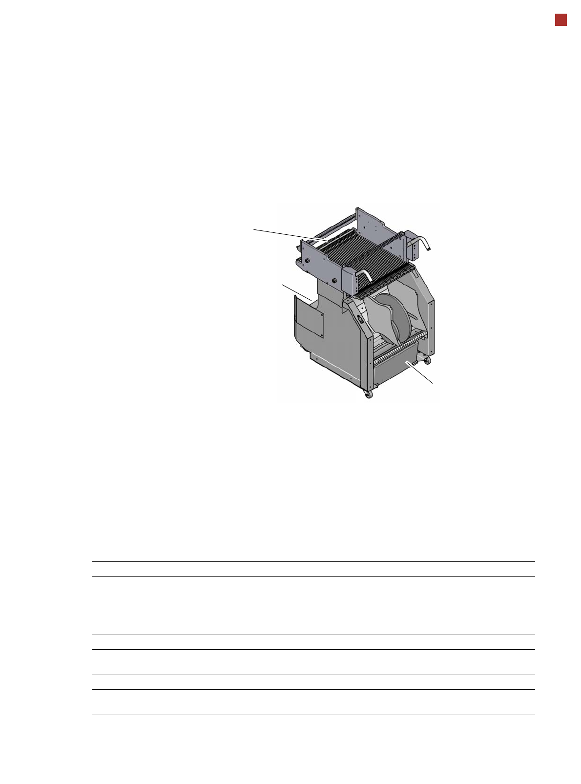
Component feeding
Component trolley
Component trolley
SIPLACE TX micron
The TX micron component
trolleys are independent and
easily maneuverable mod-
ules. Two SIPLACE TX com-
ponent trolleys, each with 40
tracks, can be docked onto
SIPLACE TX machines. The
tape reels are taken up into
the tape container of the
component trolley. A cutting
device on the machine auto-
matically cuts up the used
tape material. The compo-
nent trolleys can be set up
directly on the machine or at
an external setup area with
feeder modules. The benefits
of offline setup are that the
configurations can be pre-
pared without stopping the
line.
This allows the setup change
to be realized very quickly,
using the changeover table
principle, to rapidly change
the component trolleys.
The SIPLACE TX micron
component trolleys also sup-
port fast setting up and tear-
ing down of feeder modules
even during the ongoing
placement process.
Tapes can be spliced without
stopping the machine.
For safety reasons, unoccu-
pied locations are fitted with
so-called dummy feeder
modules.
Component trolleys for SIPLACE TX micron
Tape container
Waste container for remaining
empty tape
Changeover table
Component supply Tracks occupied
SIPLACE TX micron
With C&P20 M2
With CPP M
With CPP M and JTF-ML 2 at location 1
With C&P20 M2 and TF-ML 2 at location 1
38 feeder modules, each with 8mm X
40 feeder modules, each with 8 mm X
28 feeder modules, each with 8 mm X
28 feeder modules, each with 8 mm X
Tape reel diameter to 330.2 mm (13")
Changeover time for component trolley < 1 minute
Feeder module types Tape feeder modules, LDU 2 X,
SIPLACE Glue Feeder