GXH_1.pdf - 第13页
SS-1153 1st Edition Issued Sep., 2003 Copy ing Prohibited 4th Edition Issued Jun., 2004 Compiled and Dis tributed by 0406-004 Tg0911-W O-SP
9
SS-1153
3.2 Electrical Specifications
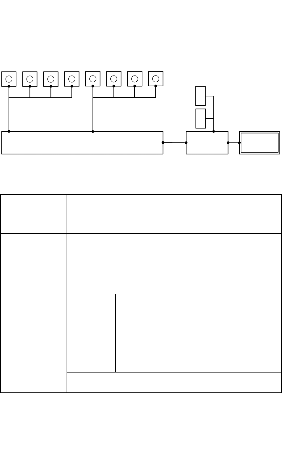
3.2.1 Control Configuration
Comera for Component
Recognition
Camera for P.E.C.
Recognition
Recognition Processor
Main Machine
Controller
Main Machine
of GXH
Monitor can be used both as operation
and recognition
(fitted with a touch screen)
Front Side
Rear Side
L
C
D
L
C
D
1
2
3
4
1
2
3
4
Fig. 1.2
3.2.2 Electrical Specifications
1. Memory Capacity
of Pattern Program
Data
Max. Number of Steps : 20,000 steps/ model
Max. Memorized Number of Models : 500 models
Note : The above numbers may be limited according to the capacity of the
pattern program data per model.
2. Input and Output
System of Pattern
Program Data
• Pattern program data editing is possible, using the touch screen, the keyboard,
and the pointing device of the main machine.
• Pattern program data can be edited with the network terminal (Option).
• Data can be entered through the local area network (Ethernet) running from
the storage unit of the network terminal (Option).
• Data Reading Floppy Disk (Option)
• Data Transfer Storage of Network Terminal (Option)
Visual Field φ 62 mm
The dimension in Y direction must be 46.5 mm.
Photoimage Front Lighting System
(Direct Recognition of Component by Front Lighting)
Back Lighting System
(Recognition with Silhouette of Component:
Limited to certain types of components)
Note: Some limitation is imposed, depending on the types
of components.
3. Component
Recognition
Note : A proper camera is automatically selected according to the shape and
size of components.
0406-004 Tg0911-WO-SP
10
SS-1153
Visual Field
Approx. 12 × 12 mm
Window Size
1.0 × 1.0 to 5.0 × 5.0 mm
Recognition
(Process) Time
Approx. 0.06 seconds / mark
(incl. the time to capture an image)
4. P.E.C. Recognition
Photoimage Front Lighting System
(Recognition of Fiducial Mark by Front Lighting)
("Normal" or "Reverse" can be selected for each mark.)
5. Setting of Fiducial
Mark
Put fiducial marks on two or three places of PCB (2 fiducial marks required for
each unit PCB of a multi-unit PCB)
By recognizing the fiducial marks using the P.E.C. recognition camera,
positional deviation covering the whole area of PCB and expansion of printed
patterns on PCB can be corrected. When the 2-point recognition mode is
selected, put fiducial marks diagonally on two places of PCB for better
recognition accuracy. In case of 3-point recognition mode, put two fiducial
marks diagonally and one fiducial mark close to one of the remaining corners.
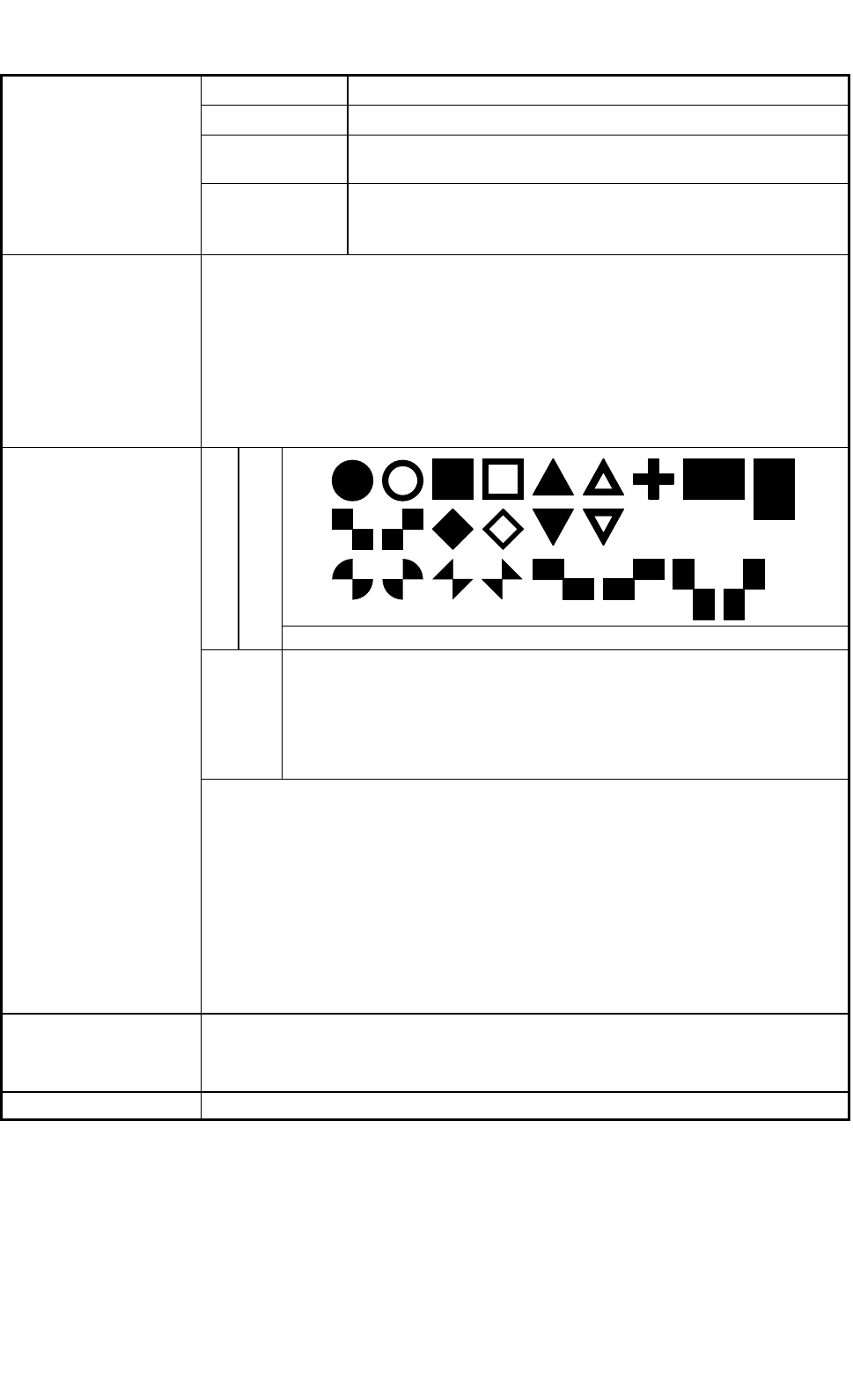
Shapes
Fiducial Marks
Size : 0.5 to 3.0 mm or less
Material
• Copper Leaf
• Ni Plating
• Solder Plating
• Solder Leveler
• Au Plating
6. Fiducial Marks
Notes : (a) The fiducial mark should make ample contrast with the
surroundings.
(b) A test may be required when the fiducial mark cannot be
recognized because of the large warpage of the PCB.
(c) Anything like a pattern similar to a fiducial mark should not exist
in the designated window. If exists, it may cause a false
recognition.
The shape (a cutout, a punched hole) of the PCB, the light reflected
from a structure, or the light emitted from the external elements
may sometimes interfere with the recognition.
7. Power Supply
200 ± 20 V AC, 3-Phase, 50/60 Hz
Connected to the power supply unit (3-phase 4-wire system).
(One of the four wires is used as a ground wire.)
8. Apparent Power Approx. 12.5 kVA
0406-004 Tg0911-WO-SP0406-001 Tg0911-WO-SP

SS-1153
1st Edition Issued Sep., 2003 Copying Prohibited
4th Edition Issued Jun., 2004
Compiled and Distributed by
0406-004 Tg0911-WO-SP