GXH_1.pdf - 第3页
1 SS-1153 1. Scope This m achine is provided w ith a batch recog nition system by w hich various kinds of electronic com ponents (sim pl y called "Com ponents" hereinafter) can be recogniz ed in batch (nonstop …

SS-1153
1. Scope ・・・・・・・・・・・・・・・・・・・・・・・・・・・・・・・・・・・・・・・・・・・・・・・・・・・・・・・・1
2. Features ・・・・・・・・・・・・・・・・・・・・・・・・・・・・・・・・・・・・・・・・・・・・・・・・・・・・・・1
3. Specifications ・・・・・・・・・・・・・・・・・・・・・・・・・・・・・・・・・・・・・・・・・・・・・・・・・・5
3.1 Mechanical Specifications ・・・・・・・・・・・・・・・・・・・・・・・・・・・・・・・・・・・5
3.1.1 Mechanical Construction ・・・・・・・・・・・・・・・・・・・・・・・・・・・・・・・・5
3.1.2 Mechanical Specifications ・・・・・・・・・・・・・・・・・・・・・・・・・・・・・・・5
3.2 Electrical Specifications ・・・・・・・・・・・・・・・・・・・・・・・・・・・・・・・・・・・・・8
3.2.1 Control Configuration ・・・・・・・・・・・・・・・・・・・・・・・・・・・・・・・・・・・9
3.2.2 Electrical Specifications ・・・・・・・・・・・・・・・・・・・・・・・・・・・・・・・・・9
The contents described in this manual are subject to change without prior notice.
0406-002 Tg0911-WO-SP
Attention : Trademarks and Registered Trademarks
• Windows is a registered trademark of the Microsoft
Corporation in the United States and other countries.
• All other corporate and product names in this manual are
owned by and are the trademarks or registered trademarks
of their respective companies.
Neither (TM) nor (R) marks are described clearly in this
manual.
CONTENTS
Page

1
SS-1153
1. Scope
This machine is provided with a batch recognition system by which various
kinds of electronic components (simply called "Components" hereinafter) can
be recognized in batch (nonstop batch recognition) and realizes highly
accurate component placement on the PCBs at high speed.
The machine is also equipped with four beams, four heads, and four
component recognition cameras, making it possible to handle many different
kinds of components in small lots or few different kinds of component in large
lots for diversified scales of production.
The machine introduces our latest technologies such as direct drive heads,
X/Y-axis linear motor driving, etc., that have been used in the past actual
production and is provided with various functions for reduction of OOS (out
of service) time. That is the reason why this high-speed mounter is called
"Direct Drive Modular Mounter with High Total Productivity for Next
Generation".
2. Features
Realization of High Productivity
• Each head has 12 nozzles and the shuttling frequency of the beams is
reduced, realizing high throughput.
• Linear motors are used to drive the X/Y axes, realizing the highly accurate
and reliable component placement at high speed.
• The nonstop batch recognition system realized the high-speed and highly
accurate recognition of components.
Collective Image Capture of 12 Components
(Example: 0603 to 4532)
• Realization of "2.5 seconds or less" (PCB Transfer Speed with PCB Size
155 mm or less)
• The tape feeders are driven by the motors, realizing the high-speed and
reliable tape feeding performance.
0401-002 Tg0911-WO-SP
2
SS-1153
• The bank feeder change carts made it possible to reduce the feeder setup
time.
• The tape splicing function is adopted to keep the machine running for
continuous production.
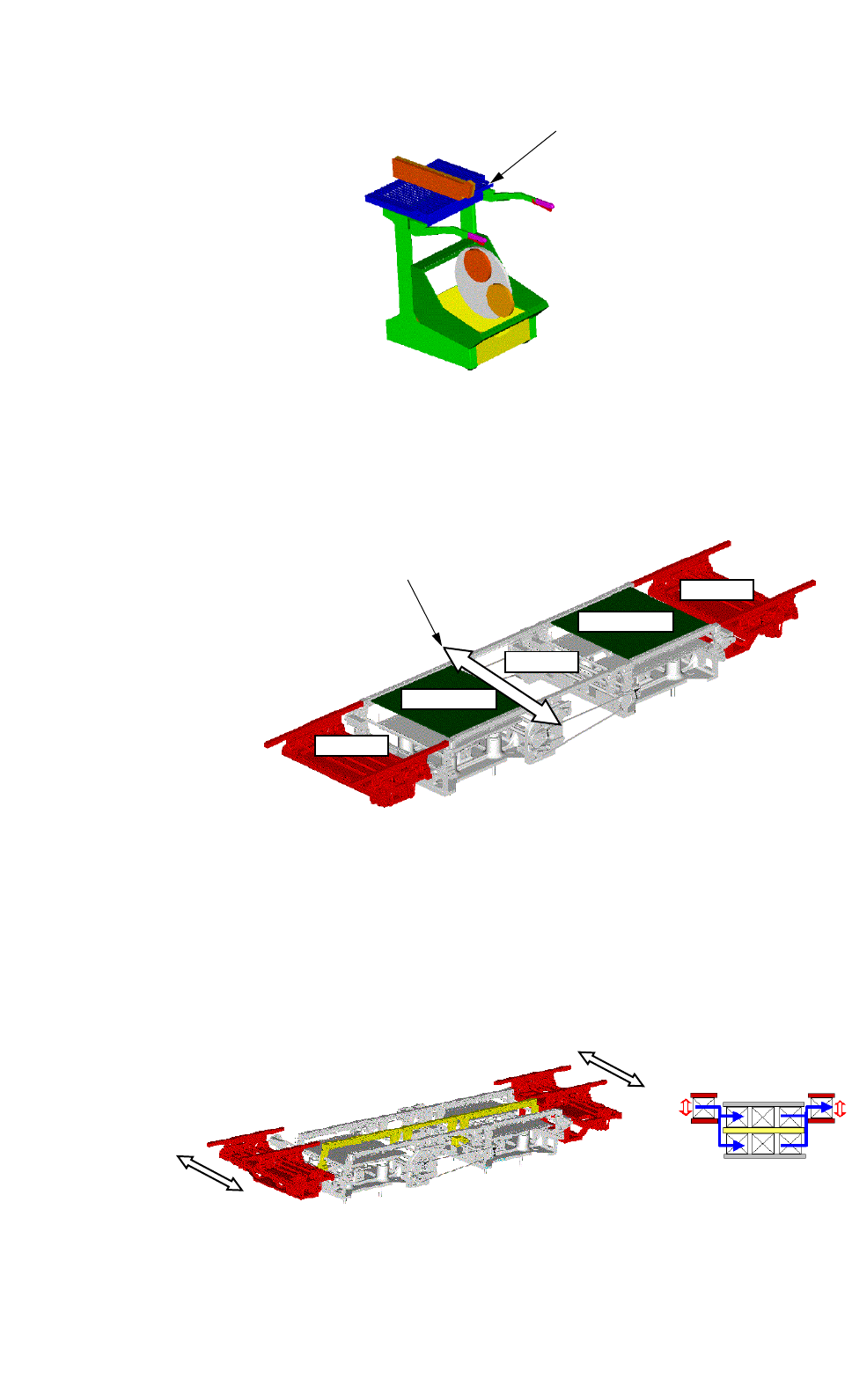
• The PCB Y position can be optimized to reduce the loss in cooperative
actions of the confronting beam.
Buffer
Input
Positioning
Positioning
Output
Optimization of PCB Y Position
PCB Flow Direction: From Left to Right
• The PCB support pins can be exchanged collectively, improving the
internal setup performance.
• The internal optimization function made it possible to re-generate the
pattern program data according to the circumstantial changes for the
machine.
• When the dual transfer function (option) is used, the PCB transfer time will
be shortened.
PCB Flow Direction: From Left to Right
• The nozzle stocker equipment will make it possible to reduce the time of
nozzle replacement required when the selected production model is
changed to another one.
0402-003 Tg0911-WO-SP
Bank Feeder Change Cart