GXH_1.pdf - 第6页
4 SS-1153 Other Functions Standard Function • Com ponent Pick- Up Error Automatic Recov ery Function • Pick -up Location Teaching Function • Pick -up Priority Function • Alternate Function at Com ponent Supply Section • …
3
SS-1153
Realization of High Reliability
• Each head is equipped with a linear measure that is used to detect picked
components (including missing ones) and vertical components and measure
the thickness of components. This system realized the high-quality
mounting of minute chips (components).
• Each nozzle is provided with an electromagnetic valve to realize the
optimum control of vacuum ON/OFF actions.
High Flexibility Function
• The optional multi-functional heads (under development) for head modules
will make it possible to mount larger varieties of components.
Technology of High Precision Component Placement
• Both X and Y axes are provided with linear motors and scales to realize the
highly accurate component placement.
Adoption of Linear Motors for X/Y Beam Driving
• Servomotors are used to drive the head, making it possible to control the
head position with the encoder.
• A highly accurate mounting is always maintained by the automatic offset
teaching function, the self-calibration system, etc.
Comfortable Operation Environment
• A new operation environment is constructed and the self-diagnosis
function is enhanced, realizing the comfortable operation environment.
• When the machine was designed, the setup and maintenance work was
taken into consideration.
• The enhanced production support software realizes high productivity.
0401-002 Tg0911-WO-SP

4
SS-1153
Other Functions
Standard Function
• Component Pick-Up Error Automatic Recovery Function
• Pick-up Location Teaching Function
• Pick-up Priority Function
• Alternate Function at Component Supply Section
• Programming Sorting Function
• Pick-Up and Placement Up/Down-Axis (L-Axis) Control Function
• Pick-Up Position (X/Y) Correction Control Function
Options
• Dual Transfer Function (under development)
• Unit PCB B.B.R. Function
• Placement Coordinates Teaching Function
• Component Library Teaching Function
• Application for BGA/CSP
• Splicing Kit
• Advance Notice and Instruction of Splicing
• Multiple Languages (Mandarin Chinese)
• Network Terminal
Programming Software
Pattern Program Optimization Software
Pattern Program Conversion Software (Our Products and Machines of
Other Brands)
CAD Conversion Software
Multi-Pattern Program Line Balance Software
Production Manager Software
• ACV System
0401-001 Tg0911-WO-SP0402-003 Tg0911-WO-SP
5
SS-1153
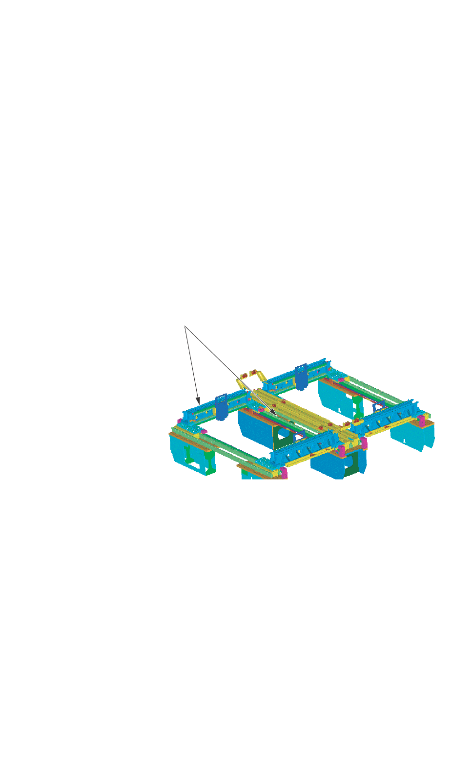
3. Specifications
3.1 Mechanical Specifications
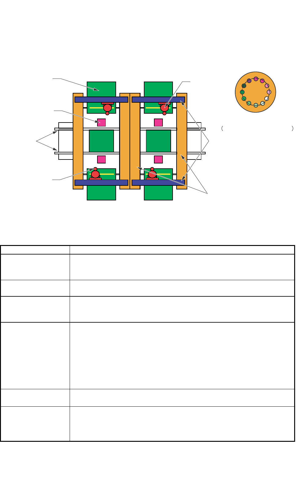
3.1.1 Mechanical Construction
Fig. 1.1
3.1.2 Mechanical Specifications
1. Model Name GXH-1
2. Throughput 62,000 CPH
Note : The placement time can be adjusted in the increments of 0.001 second,
avoiding loss time.
3. PCB Transfer
Time
Approx. 2.5 seconds (PCB Length: 155 mm or less) (under optimum condition)
4. PCB Flow
Direction and
Transfer Reference
PCB Flow Direction : From Left to Right ("From Right to Left" is optional.)
Transfer Reference : Front Side of Machine or Rear Side of Machine
5. Applicable PCB
Size: 50 × 50 to 460 × 460 mm (Four Corners : R1 to R1.5 mm)
Thickness : 0.5 to 5.0 mm
Warpage : 0.2 mm or less per 50 mm Max. ± 1 mm
Mass : Max. 1.5 kg (mass weighed when PCB is completed)
Material : Glass Epoxy
Ceramic (Option)
Note : A test is required for greater warpage, depending on the material, shape,
and mass of the PCB being used.
6. PCB Positional
Correction Method
P.E.C. Recognition
7. Conditions of PCB
before Placement
(Regulation of
Component Height)
Upper Level : Max. 12.7 mm
Lower Level : Max. 30 mm
0305-002 Tg0846-WO-SP
0304-001 Tg0846-WO-SP
0406-004 Tg0911-WO-SP
P.E.C Camera
PCB Transfer
Conveyor
Component
Recognition Camera
Feeder
X-axis
Y-axis
Head
Head Nozzle Position
Nomber of Nozzle : Max.12