GXH_1.pdf - 第8页
6 SS-1153 8. Applicable Components (1) Applicable Components Size : 0.6 × 0.3 to 44 × 44 mm or less Thickness : Max. 12.7 mm Lead Pitch : 0.4 mm pitch or more Note : Some com ponents cannot be used due to the mechanical …
5
SS-1153
3. Specifications
3.1 Mechanical Specifications
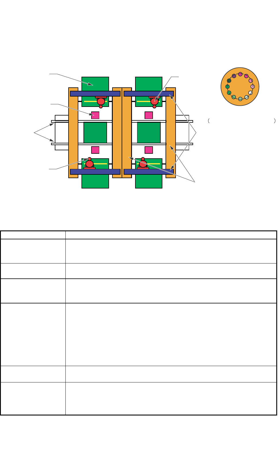
3.1.1 Mechanical Construction
Fig. 1.1
3.1.2 Mechanical Specifications
1. Model Name GXH-1
2. Throughput 62,000 CPH
Note : The placement time can be adjusted in the increments of 0.001 second,
avoiding loss time.
3. PCB Transfer
Time
Approx. 2.5 seconds (PCB Length: 155 mm or less) (under optimum condition)
4. PCB Flow
Direction and
Transfer Reference
PCB Flow Direction : From Left to Right ("From Right to Left" is optional.)
Transfer Reference : Front Side of Machine or Rear Side of Machine
5. Applicable PCB
Size: 50 × 50 to 460 × 460 mm (Four Corners : R1 to R1.5 mm)
Thickness : 0.5 to 5.0 mm
Warpage : 0.2 mm or less per 50 mm Max. ± 1 mm
Mass : Max. 1.5 kg (mass weighed when PCB is completed)
Material : Glass Epoxy
Ceramic (Option)
Note : A test is required for greater warpage, depending on the material, shape,
and mass of the PCB being used.
6. PCB Positional
Correction Method
P.E.C. Recognition
7. Conditions of PCB
before Placement
(Regulation of
Component Height)
Upper Level : Max. 12.7 mm
Lower Level : Max. 30 mm
0305-002 Tg0846-WO-SP
0304-001 Tg0846-WO-SP
0406-004 Tg0911-WO-SP
P.E.C Camera
PCB Transfer
Conveyor
Component
Recognition Camera
Feeder
X-axis
Y-axis
Head
Head Nozzle Position
Nomber of Nozzle : Max.12
6
SS-1153
8. Applicable
Components
(1) Applicable Components
Size : 0.6 × 0.3 to 44 × 44 mm or less
Thickness : Max. 12.7 mm
Lead Pitch : 0.4 mm pitch or more
Note : Some components cannot be used due to the mechanical characteristics,
shapes, etc.
Applicable Components for Reference
• Cylindrical Components
Resistors, Capacitors, Diodes
and other similar-shaped components
• Square Components
Resistors, Laminated Capacitors, Coils,
Chip Ceramic Filters and other similar-shaped components
• Deform Components
Semi-Fixed Potentiometers, Trimmer Capacitors
and other similar-shaped components
• Ics
Mini-Flat ICs, Plastic Chip Carrier with Leads,
and other similar-shaped components
• Leaded Components
Mini-Mold Transistors, Mini-Power Transistors, Filters, LEDs, Diodes,
Coils, Tantalum Capacitors, Aluminum Electrolytic Capacitors,
and other similar-shaped components
• Connectors
Connectors for FFC / FPC, PCB-to-PCB Connectors,
Wire-to-PCB Connectors, PLCC Sockets,
and other similar-shaped components
• BGA/CSP Components (Option)
BGA, CSP, LGA, and other similar-shaped components
Size : Max. 44 × 44 mm
Ball Diameter : Min. φ 0.3 mm
Ball Pitch : 0.5 mm pitch or more
(2) Packaged Posture Standards
JIS or its equivalent
• Paper Tapes (Width : 8 mm)
• Embossed Tapes (Width : 8 to 32 mm)
• Reel Outer Diameter : φ 382 mm or less.
• Tray : 100 to 136 × 100 to 323 mm
Notes : (a) Some taping sizes are limited.
Some taped components cannot be used due to the mechanical
characteristics.
(b) About Feeders
Use the tape feeders used prepared specially for GXH series.
The tape, dual tape and bulk feeders for the other machines cannot
be used.
0305-002 Tg0846-WO-SP
0406-004 Tg0911-WO-SP
7
SS-1153
9. Placement Heads Equipped with 4 heads/4 beams
Vacuum Nozzle: Max. 12 nozzles on each head
Ref. : Maximum Number of Component Picks:
Component Size 5 × 4 mm or less 12
10 × 10 mm or less 6
12 × 12 mm or less 4
20 × 20 mm or less 2
44 × 44 mm or less 1
Note : There are two types of nozzles-one for high-speed component placement
and the other for middle-sized deformed component placement.
Nozzle for High-Speed Component Placement :
The diameter is φ6 mm or less. This nozzle is used for 0603
components (Size : 0603 to 20
× 20 mm).
Nozzle for Middle-Sized Deformed Component Placement :
The diameter is φ12 mm or less. The nozzle end is processed
according to the applicable components.
The nozzle can be used for the component size of up to 44 × 44
mm.
10. Number of
Stocked Nozzles
Up to Max. 12 nozzles can be stored for each head.
Notes : (a) When some additional stockers are purchased, up to 48 nozzles can
be stored for each head.
(b) When the vacuum nozzles for the middle-sized deformed
components are used, the nozzle stockers for them are also
required.
11. Number of
Installable Feeders
Max. 100 feeders (25 feeders × 4 feeder bases)
(When only 8 mm dual tape feeders are used)
Ref. : Up to 200 types of components can be used.
Max. 100 feeders (when only 12/16 mm tape feeders are used)
Max. 48 feeders (when only 24/32 mm tape feeders are used)
Notes : (a) The number of installable feeders varies according to the
combination of the reel width for the taping and the feeders.
(b) Use the tape feeders used prepared specially for GXH series.
The tape, dual tape and bulk feeders for the other machines cannot
be used.
Supply Pressure 0.45 to 0.69 MPa (4.6 to 7 kgf/cm ²)
Set Pressure 0.45 MPa (4.6 kgf/ cm²)
Note : Min. 0.4 MPa (4.1 kgf/ cm²) of air pressure is
necessary for operation.
12. Air Supply
Note : Use the dry and clean air as follows
Moisture : Dew Point −17°C or lower (Atmospheric Pressure)
Oil : 0.1 mg/m
3
or less (ANR)
Dust : Solid Material 0.01 µm or less
13. Air Consumption Approx. 160 L/min (Normal)
14. Vacuum Pressure
−93 kPa (70 cmHg)
0406-004 Tg0911-WO-SP
0406-004 Tg0911-WO-SP