GXH_1.pdf - 第9页
7 SS-1153 9. Placement H eads Equipped with 4 heads/4 beam s Vacuum N ozzle: Max. 12 nozz les on each head Ref. : Maximum Num ber of Component Pick s: Component Siz e 5 × 4 mm or less 12 10 × 10 mm or less 6 12 × 12 mm o…
6
SS-1153
8. Applicable
Components
(1) Applicable Components
Size : 0.6 × 0.3 to 44 × 44 mm or less
Thickness : Max. 12.7 mm
Lead Pitch : 0.4 mm pitch or more
Note : Some components cannot be used due to the mechanical characteristics,
shapes, etc.
Applicable Components for Reference
• Cylindrical Components
Resistors, Capacitors, Diodes
and other similar-shaped components
• Square Components
Resistors, Laminated Capacitors, Coils,
Chip Ceramic Filters and other similar-shaped components
• Deform Components
Semi-Fixed Potentiometers, Trimmer Capacitors
and other similar-shaped components
• Ics
Mini-Flat ICs, Plastic Chip Carrier with Leads,
and other similar-shaped components
• Leaded Components
Mini-Mold Transistors, Mini-Power Transistors, Filters, LEDs, Diodes,
Coils, Tantalum Capacitors, Aluminum Electrolytic Capacitors,
and other similar-shaped components
• Connectors
Connectors for FFC / FPC, PCB-to-PCB Connectors,
Wire-to-PCB Connectors, PLCC Sockets,
and other similar-shaped components
• BGA/CSP Components (Option)
BGA, CSP, LGA, and other similar-shaped components
Size : Max. 44 × 44 mm
Ball Diameter : Min. φ 0.3 mm
Ball Pitch : 0.5 mm pitch or more
(2) Packaged Posture Standards
JIS or its equivalent
• Paper Tapes (Width : 8 mm)
• Embossed Tapes (Width : 8 to 32 mm)
• Reel Outer Diameter : φ 382 mm or less.
• Tray : 100 to 136 × 100 to 323 mm
Notes : (a) Some taping sizes are limited.
Some taped components cannot be used due to the mechanical
characteristics.
(b) About Feeders
Use the tape feeders used prepared specially for GXH series.
The tape, dual tape and bulk feeders for the other machines cannot
be used.
0305-002 Tg0846-WO-SP
0406-004 Tg0911-WO-SP
7
SS-1153
9. Placement Heads Equipped with 4 heads/4 beams
Vacuum Nozzle: Max. 12 nozzles on each head
Ref. : Maximum Number of Component Picks:
Component Size 5 × 4 mm or less 12
10 × 10 mm or less 6
12 × 12 mm or less 4
20 × 20 mm or less 2
44 × 44 mm or less 1
Note : There are two types of nozzles-one for high-speed component placement
and the other for middle-sized deformed component placement.
Nozzle for High-Speed Component Placement :
The diameter is φ6 mm or less. This nozzle is used for 0603
components (Size : 0603 to 20
× 20 mm).
Nozzle for Middle-Sized Deformed Component Placement :
The diameter is φ12 mm or less. The nozzle end is processed
according to the applicable components.
The nozzle can be used for the component size of up to 44 × 44
mm.
10. Number of
Stocked Nozzles
Up to Max. 12 nozzles can be stored for each head.
Notes : (a) When some additional stockers are purchased, up to 48 nozzles can
be stored for each head.
(b) When the vacuum nozzles for the middle-sized deformed
components are used, the nozzle stockers for them are also
required.
11. Number of
Installable Feeders
Max. 100 feeders (25 feeders × 4 feeder bases)
(When only 8 mm dual tape feeders are used)
Ref. : Up to 200 types of components can be used.
Max. 100 feeders (when only 12/16 mm tape feeders are used)
Max. 48 feeders (when only 24/32 mm tape feeders are used)
Notes : (a) The number of installable feeders varies according to the
combination of the reel width for the taping and the feeders.
(b) Use the tape feeders used prepared specially for GXH series.
The tape, dual tape and bulk feeders for the other machines cannot
be used.
Supply Pressure 0.45 to 0.69 MPa (4.6 to 7 kgf/cm ²)
Set Pressure 0.45 MPa (4.6 kgf/ cm²)
Note : Min. 0.4 MPa (4.1 kgf/ cm²) of air pressure is
necessary for operation.
12. Air Supply
Note : Use the dry and clean air as follows
Moisture : Dew Point −17°C or lower (Atmospheric Pressure)
Oil : 0.1 mg/m
3
or less (ANR)
Dust : Solid Material 0.01 µm or less
13. Air Consumption Approx. 160 L/min (Normal)
14. Vacuum Pressure
−93 kPa (70 cmHg)
0406-004 Tg0911-WO-SP
0406-004 Tg0911-WO-SP
8
SS-1153
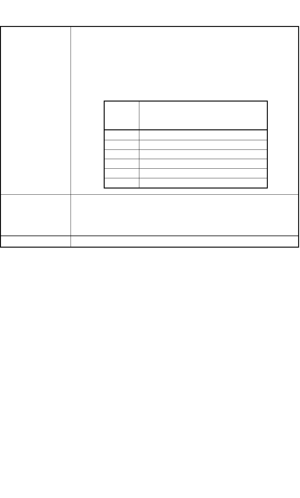
15. Environmental
Condition
Temperature: 20
±
10
°
C
Humidity : 30 to 80 % (Avoid dew condensation)
Note : When the ambient temperature rises more than the surface of the
machine, dew may condense under the condition described below.
Note that dew condensation may cause the machine to break down.
Condition of Dew Condensation
Dew may condense when the differences (based on "Humidity (%)")
between the ambient and surface temperatures of the machine reach the
values or more in the table below.
16. Dimensions
Approx. 2,664 (width) × 2,350 (depth) × 1,400 (height) mm
Notes : (a) The width includes the conveyor.
(b) The depth becomes 2,578 mm when the Bank Feeder Change Cart
is included.
(c) The height becomes 2,100 mm when the light tower is included.
17. Mass Approx.
3,000 kg (excl. the Bank Feeder Change Carts and the tape feeders)
Humidity
(%)
Differences between Ambient and Surface
Temperatures of Machine (Ambient
Temperature > Surface Temperature)
80 3 °C or more
70 6 °C or more
60 8 °C or more
50 10 °C or more
40 14 °C or more
30 18 °C or more
0406-004 Tg0911-WO-SP