CP40 service manual.pdf - 第85页
1. Head Part (CP-40) 200 SET RESET SET Ripple C ontrol Control SW Connecting Cable 0 SET BOARD SW2 VR3 SW1 VR2 V R1 No.1 No.2 No.3 (Fig. 1) J1 1-3-3. Align Set_Up Version Date WA QA CA Note 00 Nov04 O
1. Head Part
(CP-40)
1-3-2. Align Replacement
Wori Aligner
J9059008A
Flat-head Screwdriver
CAP
Hexagon
Wrench Bolt
M4 Hexagon Wrench
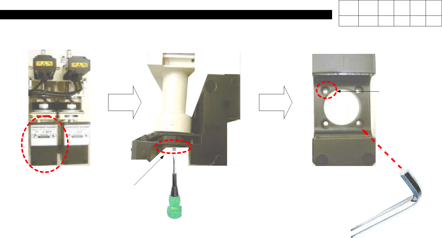
1) Disconnect Connector on the Top of
Aligner (In Orders of Head 1, Head 2,
Head3fromLeft).
2) Using a Flat-head Screwdriver, Press
Left and Right Sides of Cap to
Remove Cap.
3) Using a M4 Hexagon Wrench, Loosen
4 Hexagon Wrench Bolts and Replace
Aligner.
Version Date WA QA CA Note
00 Nov04 O
1. Head Part
(CP-40)
200 SET
RESET
SET
Ripple Control
Control SW
Connecting Cable
0 SET
BOARD
SW2 VR3 SW1 VR2 VR1
No.1
No.2 No.3
(Fig. 1)
J1
1-3-3. Align Set_Up
Version Date WA QA CA Note
00 Nov04 O
1. Head Part
(CP-40)
WA
COMP ASS'Y
(Adjustment Procedures)
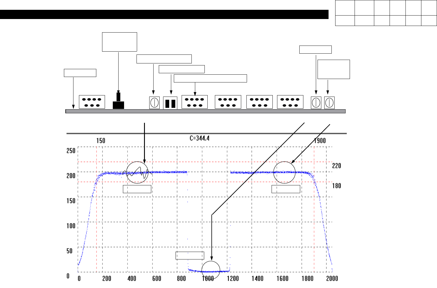
# Connect J1 and Mother Board.
1) Set Control SW(SW1) to UP.
2) Press SW2 to RESET.
3) Open C:\SACOM File.
4) Perform Light ON OFF TEST for Aligner at Function.
5) Align COMP ASS'Y with Aligner Bottom.
# IMAGE DROW => Profile Open
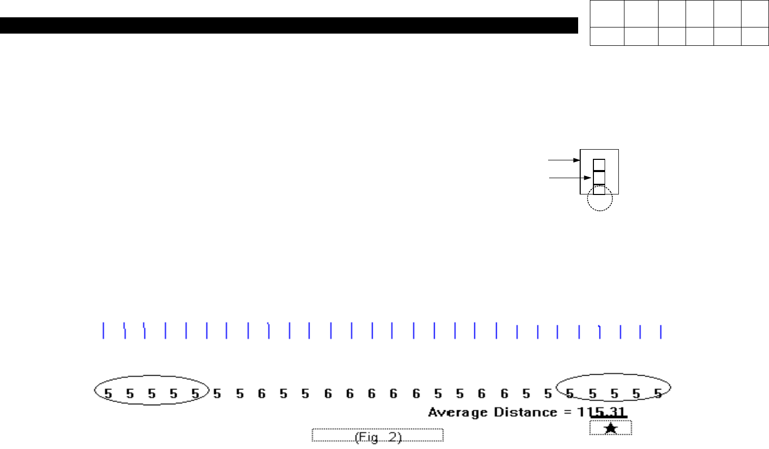
6) Adjust VR2 to Set Waveform to 0.
7) Adjust VR3 to Set Ripple Waveform to Some.
8) Adjust VR1 to Set Waveform to 200.
Version Date WA QA CA Note
00 Nov04 O O O