196396 Iss 2 Nov 2015 - Semi Appendix Manual.pdf - 第119页
PREVENTIVE MAINTENANCE MONTHLY MAINTENANCE 28.58 Technical Reference Manual Chapter Issue 5, Aug 14 SEMI Level TRS Pull Down Reference For k Grooves Tick Inspect for wear , clean and apply a small amount of grease around…
PREVENTIVE MAINTENANCE
MONTHLY MAINTENANCE
Chapter Issue 5, Aug 14 Technical Reference Manual 28.57
Monthly Hardware Check
SEMI Level Screen Alignment Tick
Inspect the wiring and connections.
Inspect the three striker plates, clean and apply a wipe of light grease.
Check all actuators home correctly.
SEMI1
SEMI 2
SEMI Level Screen Change Tick
Remove and clean the auto drip tray.
Fully extend the auto drip tray telescopic plungers and clean.
Clean the screen stop actuator arm lever.
Clean the screen at stop sensor.
Refit the auto drip tray and check operation of the screen change mechanism.
SEMI1
SEMI 2
SEMI Level Chase Tick
Inspect the condition of wiring/pneumatic connections.
Clean and lubricate with light oil, the omni track bearings and the underside of the track
plates.
Clean the left and right screen at centre optos.
Clean the stencil guide strips of debris/paste.
Remove the ASM pneumatic cylinder covers.
Ensure ASM cable assembly is seated correctly around all pulleys.
Loosen cable retainer bracket securing screws. Adjust position of bracket to eliminate any
cable slack.
Ensure all screen clamps are at their home position. Tighten retainer bracket securing
screws.
Refit ASM pneumatic cylinder covers.
Check operation of the chase clamps.
Check operation of the ASM.
SEMI1
SEMI 2
PREVENTIVE MAINTENANCE
MONTHLY MAINTENANCE
28.58 Technical Reference Manual Chapter Issue 5, Aug 14
SEMI Level TRS Pull Down Reference Fork Grooves Tick
Inspect for wear, clean and apply a small amount of grease around the fork groove of the
brace assembly forks.
SEMI Level Topside Referencing System Tick
Check the action of the stripper springs, replace if motion is slow or damage is evident.
Replace the z-lock return springs. When refitting, ensure they are intact, not damaged and
not stretched.
Replace the TRA cylinder springs. When refitting, ensure they are intact, not damaged and
not stretched.
Check the electrical and pneumatic looms to the Z-lock, Rail Cap, Reference Cylinders,
TRA cylinders and the Pusher Plate are not damaged. Replace as necessary.
Replace the return springs on the active surround. When refitting, ensure they are intact,
not damaged and not stretched.
Ensure that the interlock pins return against spring pressure, do not stick in the slider.
Replace if necessary.
Rail Cap Bearing Retainers for signs of damage, replace as required.
Rail Cap height above the vacuum chamber.
Estimated time required for Monthly tasks 6.0 hours
Summary/Remarks
Signed: Date:
SEMI1
SEMI 2
PREVENTIVE MAINTENANCE
CLEANING, LUBRICATION AND MAINTENANCE DIAGRAMS
Chapter Issue 5, Aug 14 Technical Reference Manual 28.59
CLEANING, LUBRICATION AND MAINTENANCE DIAGRAMS
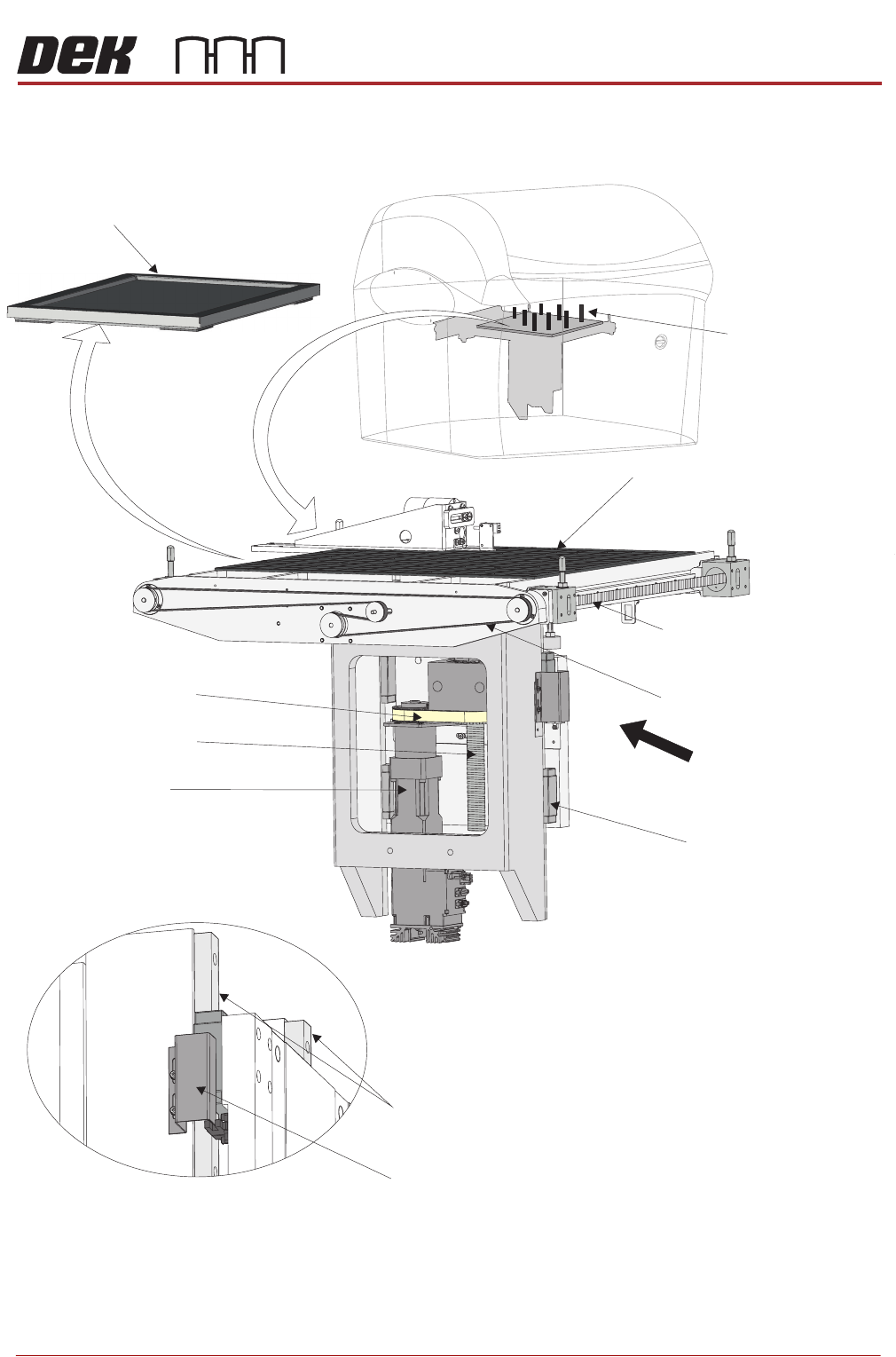
Figure 28-1 Rising Table
A
Tooling (clean)
Manual Tooling Plate (clean)
View on Rear of Rising Table
Transport Rail Drive Belt
Rising Table Drive Belt
LED Stencil Backlight Panel (clean)
Rising Table Ballscrew
Transport Rail Ballscrew
(in 2 positions)
Rising Table Motor
Linear Bearing Block
(in 4 positions)
View on Arrow A
Sensor Vane
Vertical Linear Bearing Guide Rails