196396 Iss 2 Nov 2015 - Semi Appendix Manual.pdf - 第48页
POWER SUPPLY AND DISTRIBUTION M37 POWER SUPPLY ENCLOSURE Chapter Issue 3, Nov 14 Technical Reference Manual 6.7 Printhead Cover Loop The printhead cover loop consist s of a series circuit connecting the two E S top blank…
POWER SUPPLY AND DISTRIBUTION
M37 POWER SUPPLY ENCLOSURE
6.6 Technical Reference Manual Chapter Issue 3, Nov 14
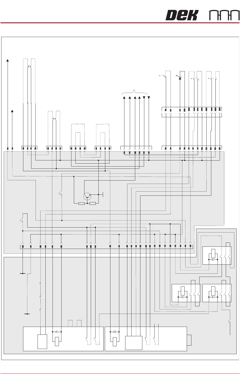
Figure 6-3 Printhead Cover Loop Circuit
2 Handed
Safety Re
lay
PIHZ X1
RL2
A1
A2
23
24
13
14
S13
S14
S23
S24
N/C
N/C
Control
Circuit
Y1 Y2
E Stop Re
lay
PNOZX2
RL1
Reset
Control
S33
S34
A1
A2
13
14
23
24
S11
S12
S21
S22
44
45
46
47
48
49
49
50
51
CB32
10A
48V dc
From PSU 2
M37 Power Supp
ly Crate
M37TB01
Power Distribution PCB
CB 6
1.5A
CB 1
3.15A
Part
CON3
Part
CON2
Part
CON1
27
28
25
26
33
34
35
17
0V
15
24V US F
rom PSU 1
36
37
38
40
39
41
42
43
M37PL23
M37PL22
1
2
24V SW
48V dc Servo Motor
Supply
14PL08
E
System
M37PL27
1
2
System
Lamp
3
4
5
6
7
8
9
10
11
12
E
Jog Left
E
Jog Right
1
2
3
4
5
6
7
8
9
10
11
12
M37PL25
1
2
5
3
M37PL24
1
2
5
3
E Stop Blanking Plug
3
4
Front
Cover
Interlock
System Power On
5
8
M37SK26
0V
M36 Machine
Controller
7
E Stop Supply
Jog Left
2
3
Jog Right
6
Cover Interlock
Rear Cover Interlock
Blanking Plug
1
2
3
4
Q1
R1
0V
R2
CON3
1
A1
A2
2
3
5
4
6
CON2
1
A1
A2
2
3
5
4
6
CON1
1
A1
A2
2
3
5
4
6
E Stop Blanking Plug

POWER SUPPLY AND DISTRIBUTION
M37 POWER SUPPLY ENCLOSURE
Chapter Issue 3, Nov 14 Technical Reference Manual 6.7
Printhead Cover
Loop
The printhead cover loop consists of a series circuit connecting the two E Stop
blanking plugs, the front cover interlock and the rear cover interlock blanking
plug. The E Stop loop supply (software E Stop) from the NextMove interface
card passes through the loop to the solenoid of the E Stop relay. Once energised
the E Stop relay feeds 24V US from PSU 1 to the solenoids of contactors Con1,
Con2 and Con3. Once energised contactor Con1 feeds 24V SW via contactor
Con3 to provide stepper motor drive. Contactor Con2 feeds +48V dc from PSU
2 via contactor Con3 to provide servo motor power.
If any component in the loop becomes open circuit or if the E Stop loop supply
drops to 0V, the E Stop relay PNOZ X2 de-energises. Contactors Con1, Con2
and Con3 de-energise, this ensures the immediate shut down of all motors.
On opening the printhead cover, the machine monitor displays the ‘Machine
Operation Suspended - Cover Open’ window. The recovery method is to
close the printhead cover and press the System button.
Two-Handed Relay With the front printhead cover open the machine sees this as an error condition
and motor power is not available. The two-handed relay enables functions such
as priming paper and priming solvent to be carried out with the front printhead
cover open. The operator selects the required function on the MMI prior to
opening the front printhead cover. Once selected both jog buttons are used to
perform the task.
Provided the two jog buttons are pressed within 0.5 seconds of each other, the
two-handed safety relay internal control circuit allows the safety relay contacts
to switch. Contactors Con1 and Con3 activate to enable the 24V SW supply. As
contactor Con2 does not become energized, power is not available for servo
motor drive.
The 24V SW power is enabled whilst the jog buttons are held on. The software,
having being notified that a prime paper or prime solvent function has been
selected, provides drive to the relevant circuit.
System Switch Provided the printhead cover loop is intact, the E Stop loop supply is at 24V and
is available at the E Stop relay solenoid. System power is controlled by the
system switch which is connected to the reset terminals of the E Stop relay
control circuit. Internal auxiliary contacts Con1, Con2 and Con3 are wired in
series with the system switches, this allows the E Stop relay to monitor the
contactors to ensure that they have not welded shut.
By pressing and releasing the system switch, the relay control circuit enables
the activation of the 24V switching contacts and power is available to contactors
Con1, Con2 and Con3. Contactor Con2, via contactor Con3, enables system
power to be available and this is signalled to the control enclosure with the
switching on of Q1. With the 24V SW supply now available, the system lamp
comes on and stays on even though the system switch has been released.
Contactor Con2, via contactor Con3, also enables the 48V dc servo motor
supply.
POWER SUPPLY AND DISTRIBUTION
M37 POWER SUPPLY ENCLOSURE
6.8 Technical Reference Manual Chapter Issue 3, Nov 14
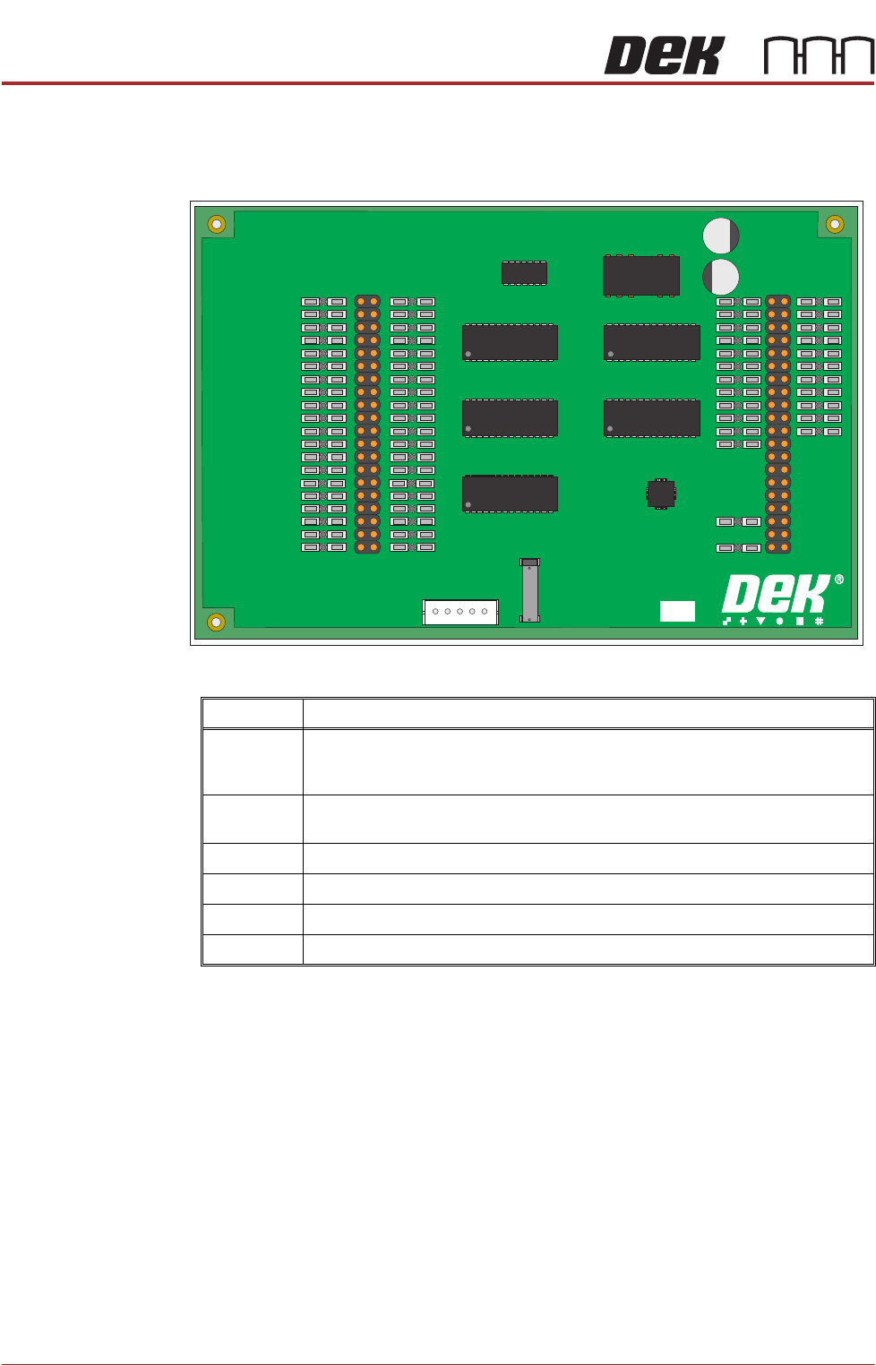
PSU Monitor Board The board monitors the voltages at circuit breakers CB1 - CB31 on the power
distribution PCB and sends a data stream via the USB port M37SK30 to the
machine PC.
The voltages monitored and where used are as follows:
A separate application is used to display the voltage readings on the machine
monitor, to access this window carry out the following:
1. Switch ON and initialise the machine.
2. On the keyboard, press the Windows key to access the taskbar.
PSU MONITOR BOARD
181507 ISSUE
Voltage Where Used
+24V US NextMove Interface, Camera Lighting, Stepper Logic, Machine Fans, I/O Node
Power, Grid-Lok Tooling, High Throughput Conveyor (HTC), Euroflex and Servo
Motor Logic.
+24V SW NextMove Interface, Belt Motors, I/O Node Power, Grid-Lok Tooling and High
Throughput Conveyor (HTC).
+5.5V NextMove ES, USB Hub
+12V I/O Node Power, Grid-Lok Tooling and High Throughput Conveyor (HTC).
-12V NextMove ES
+42V/+48V Servo Motor Supply