196396 Iss 2 Nov 2015 - Semi Appendix Manual.pdf - 第133页
PREVENTIVE MAINTENANCE CLEANING, LUBRICATION AND MAINTENANCE DIAGRAMS 28.72 Technical Reference Manual Chapter Issue 5, Aug 14 Figure 28-14 Unde rscreen Cleaner View fr o m L eft S ide o f M a c hine Camera Y Linear Bear…
PREVENTIVE MAINTENANCE
CLEANING, LUBRICATION AND MAINTENANCE DIAGRAMS
Chapter Issue 5, Aug 14 Technical Reference Manual 28.71
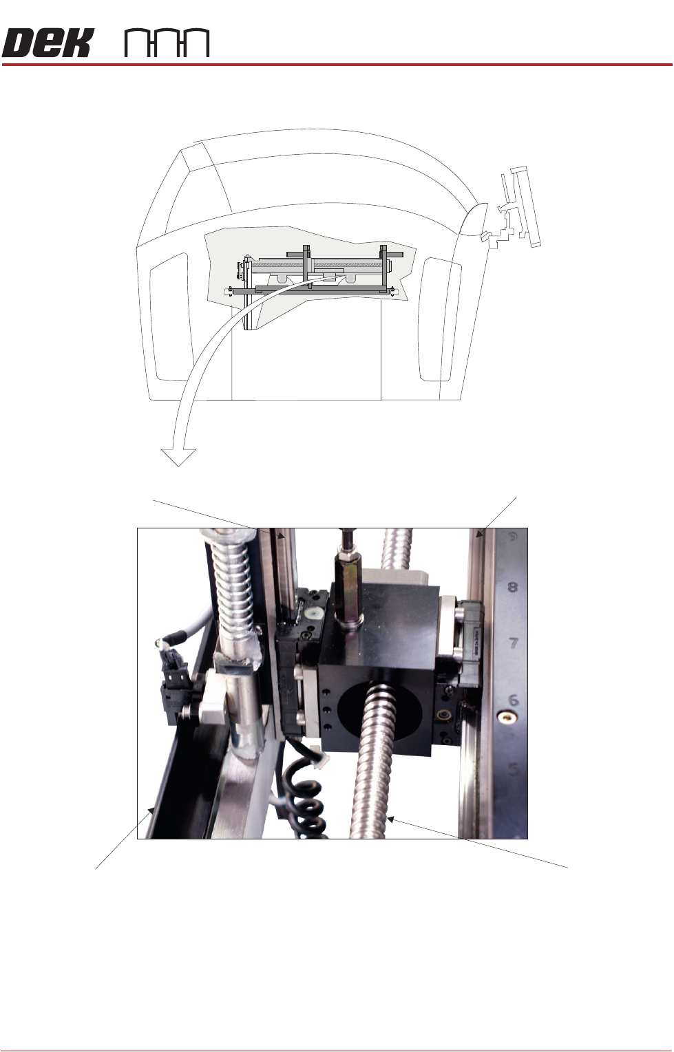
Figure 28-13 Rail System
Horizontal Linear Bearing
Guide (in 2 positions)
Ballscrew
(in 2 positions)
Clatter Bar
(in 2 positions)
Vertical Linear Bearing
Guide (in 4 positions)
Plan View on Rail Drive System
View on Left Side of Machine
PREVENTIVE MAINTENANCE
CLEANING, LUBRICATION AND MAINTENANCE DIAGRAMS
28.72 Technical Reference Manual Chapter Issue 5, Aug 14
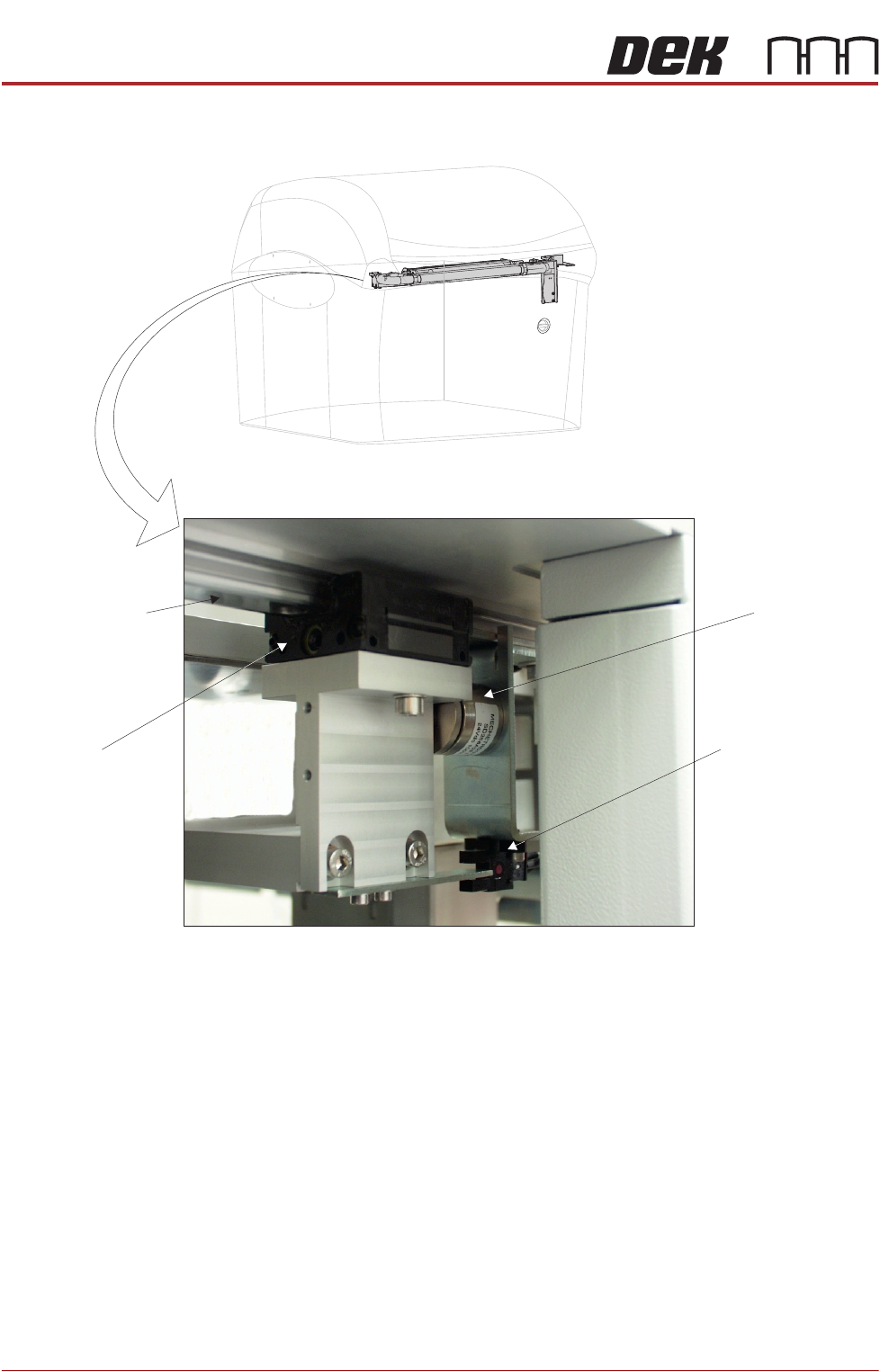
Figure 28-14 Underscreen Cleaner
View from Left Side of Machine
Camera Y Linear
Bearing Guide Rail
(in 2 positions)
USC Linear
Bearing Block
(in 2 positions)
USC Magnet
(in 2 positions)
USC Home Sensor
PREVENTIVE MAINTENANCE
CLEANING, LUBRICATION AND MAINTENANCE DIAGRAMS
Chapter Issue 5, Aug 14 Technical Reference Manual 28.73
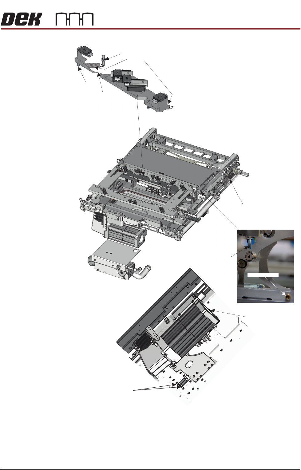
Figure 28-15 Topside Referencing System (TRS)
Cylinder Springs (4)
Stripper Spring (2)
Lock Pin (2)
View from Beneath the Assembly
Front of Printer
Z-Lock Return Springs
Z-Lock Cylinders
Anchor Pillar
Post
Cut-away to show
spring beneath
pusher plate
Return Spring