196396 Iss 2 Nov 2015 - Semi Appendix Manual.pdf - 第46页
POWER SUPPLY AND DISTRIBUTION M37 POWER SUPPLY ENCLOSURE Chapter Issue 3, Nov 14 Technical Reference Manual 6.5 Printhead Cover Loop Component s The printhead cover loop circuit comprises the following: • The E S top Rel…
POWER SUPPLY AND DISTRIBUTION
M37 POWER SUPPLY ENCLOSURE
6.4 Technical Reference Manual Chapter Issue 3, Nov 14
M37 POWER SUPPLY ENCLOSURE
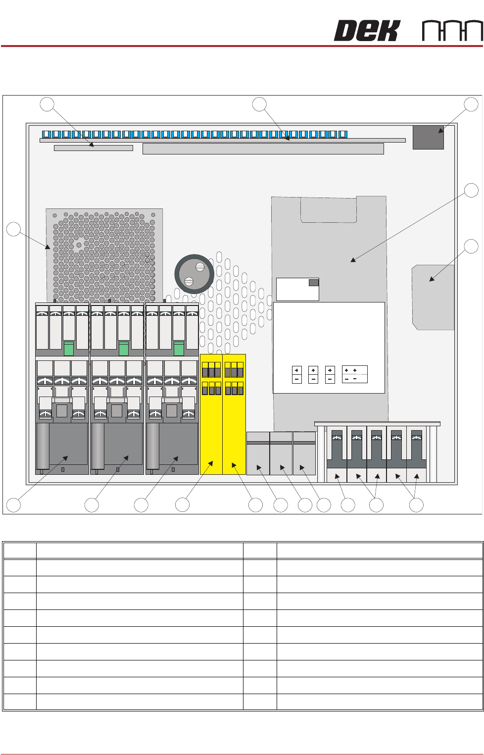
Figure 6-1 M37 Power Supply Enclosure Layout - Plan View
Item Description Item Description
1 Mains Power Output Sockets 10 2 Handed Safety Relay
2 Power Supply Unit PSU 1 11 E Stop Relay
3 Internal Vacuum Pump Mains Filter 12 Contactor Con1
4 Circuit Breaker CB34 13 Contactor Con2
5 Circuit Breaker CB33 14 Contactor Con3
6 Circuit Breaker CB32 15 Power Supply Unit PSU 2
7 Terminal Block TB3 16 PSU Monitor Board
8 Terminal Block TB2 17 Power Distribution PCB
9 Terminal Block TB1
1
2
3
4
5
6
7
8
9
10
11
12
13
14
15
16
17
POWER SUPPLY AND DISTRIBUTION
M37 POWER SUPPLY ENCLOSURE
Chapter Issue 3, Nov 14 Technical Reference Manual 6.5
Printhead Cover
Loop Components
The printhead cover loop circuit comprises the following:
• The E Stop Relay
• The Two-Handed Relay
• System Switch
• Front Cover Interlock Switch
• Rear Cover Interlock Blanking Plug
• Printhead Cover Loop Circuit
• E Stop Blanking Plug (in 2 positions)
• Jog Buttons
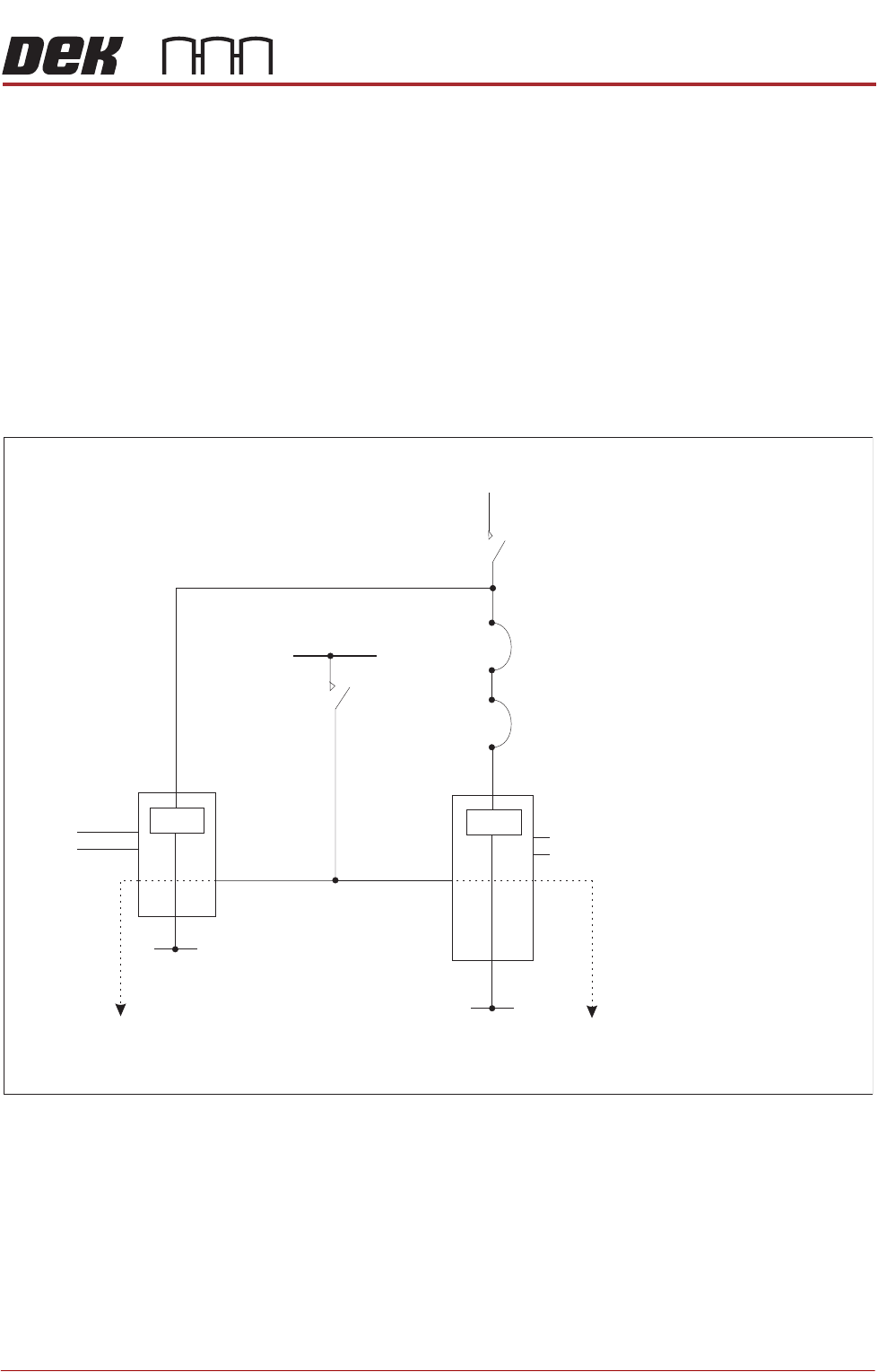
Figure 6-2 Simplified Printhead Cover Loop Circuit
CON1
AUX
CON2 CON3 Sys. Switch
AUX AUX
E Stop
Relay
0V
Printhead Cover Loop and
E Stop Blanking Plug (in 2 positions)
Printhead Cover Loop Supply
(Software E Stop)
Contactors
1, 2&3
Supplies 24V SW and 48V dc to the motors
Front Cover Interlock
CB1
3.15A
24V US
2 Handed
Relay
0V
Contactors
1&3
Jog
Buttons
Supplies 24V SW to the motors
Rear Cover Interlock Blanking Plug
POWER SUPPLY AND DISTRIBUTION
M37 POWER SUPPLY ENCLOSURE
6.6 Technical Reference Manual Chapter Issue 3, Nov 14
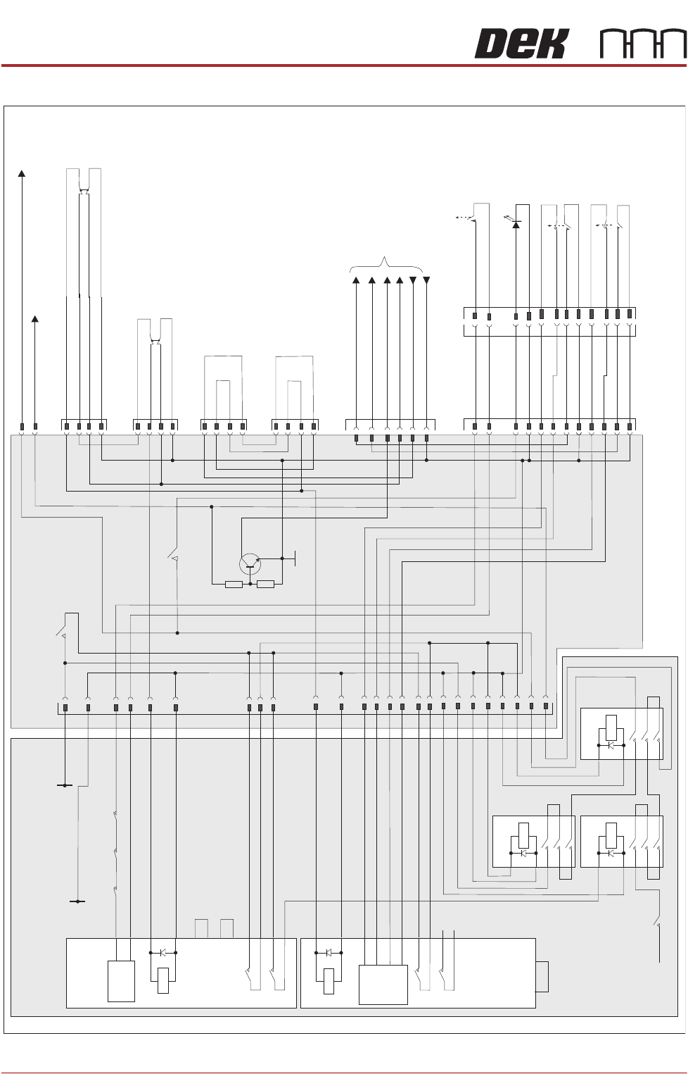
Figure 6-3 Printhead Cover Loop Circuit
2 Handed
Safety Re
lay
PIHZ X1
RL2
A1
A2
23
24
13
14
S13
S14
S23
S24
N/C
N/C
Control
Circuit
Y1 Y2
E Stop Re
lay
PNOZX2
RL1
Reset
Control
S33
S34
A1
A2
13
14
23
24
S11
S12
S21
S22
44
45
46
47
48
49
49
50
51
CB32
10A
48V dc
From PSU 2
M37 Power Supp
ly Crate
M37TB01
Power Distribution PCB
CB 6
1.5A
CB 1
3.15A
Part
CON3
Part
CON2
Part
CON1
27
28
25
26
33
34
35
17
0V
15
24V US F
rom PSU 1
36
37
38
40
39
41
42
43
M37PL23
M37PL22
1
2
24V SW
48V dc Servo Motor
Supply
14PL08
E
System
M37PL27
1
2
System
Lamp
3
4
5
6
7
8
9
10
11
12
E
Jog Left
E
Jog Right
1
2
3
4
5
6
7
8
9
10
11
12
M37PL25
1
2
5
3
M37PL24
1
2
5
3
E Stop Blanking Plug
3
4
Front
Cover
Interlock
System Power On
5
8
M37SK26
0V
M36 Machine
Controller
7
E Stop Supply
Jog Left
2
3
Jog Right
6
Cover Interlock
Rear Cover Interlock
Blanking Plug
1
2
3
4
Q1
R1
0V
R2
CON3
1
A1
A2
2
3
5
4
6
CON2
1
A1
A2
2
3
5
4
6
CON1
1
A1
A2
2
3
5
4
6
E Stop Blanking Plug