Specification SIPLACE CF-Medium.pdf - 第16页
15 Desc ription If a num ber of Waf fle Packs are requir ed during a placement proc- ess, the use of the automa tic Waff le Pac k Changer ( WPC) is recommend ed. The set-up of the WPC is e xactly co or dinated wi th the …
14
Description
The manual tray feeder is one
option for picking up components
from waffle packs and matrix
trays. A number of “manual trays”
can be placed on the component
changeover tables (right-hand table
for Fine Pitch components). This
option is recommended if only a
few component types are supplied
in trays.
Component Supply:
Manual Trays
Technical Data
Sizes
136 x 360 mm
2
;
requires 5 feeder locations
260 x 360 mm
2
;
requires 9 feeder locations
Max. tray height 12.5 mm including component
Parts
Manual tray
Carrier tray
JEDEC Waffle Packs
Directly in the manual tray
136 mm wide
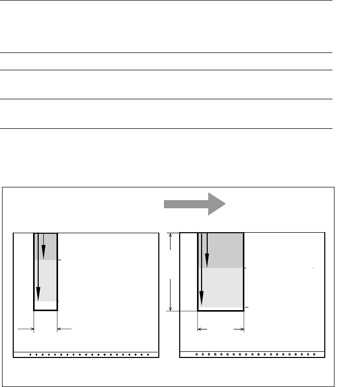
Pick & Place Head and Collect & Place Head Access to Manual Tray
Transport Direction
Collect & Place Head
Pick & Place Head
Feeder Table
136
JEDEC Magazine
119 mm
301 mm
Collect & Place
Head
Pick & Place Head
Feeder Table
260
(136)
360
Carrier Tray
157 mm
339 mm
15
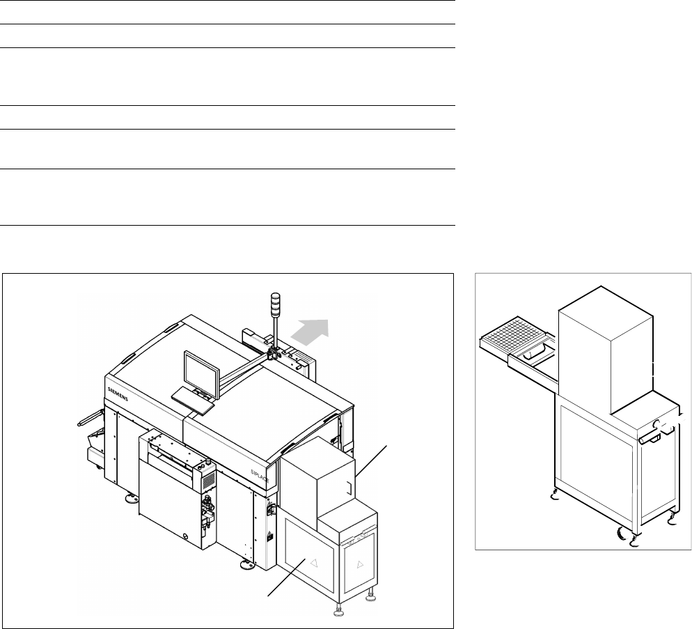
Description
If a number of Waffle Packs are
required during a placement proc-
ess, the use of the automatic
Waffle Pack Changer (WPC) is
recommended. The set-up of the
WPC is exactly coordinated with
the sequence of placement for a
work process optimized in terms
of path and time. An elevator
automatically brings the correct
magazine into the access range of
the placement head. The magazine
for the first component is changed
as soon as a PCB moves into the
placement conveyor and valid data
for cluster and set-up are available.
The remaining magazine changes
are made in slack time during
placement. The magazines can be
replenished without any machine
idle time. The placement head
puts faulty components back
where it picked them up.
A narrow component table with
10 locations for feeder modules is
also available on the tray changer
(sample capacity: 20 tracks of
8 mm each).
Component Supply:
Waffle Pack Changer
Technical Data
Contents of storage 28 carrier trays for Waffle Packs
Max. magazine size 240 x 340 mm
2
Max. tray size
6-Nozzle Collect & Place Head
Pick & Place Head
≤ JEDEC Tray
≤ 240 x 340 mm
2
Magazine height 15 mm including component
Max. number of
component types 200 per Waffle Pack Changer
Changing time
per magazine
< 3 s
parallel to other substeps during a
placement cycle
Waffle Pack Changer
SIPLACE CF with Waffle Pack Changer
Waffle Pack
Changer
PCB
Transport
Direction
10 Feeder
Positions
16
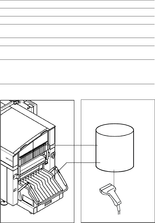
Description
The bar code scanner enables a
quick and reliable check of com-
ponent set-up and refill. The bar
codes of the tracks and the loaded
components assigned to the
tracks (bar code labels on tapes,
Bulk Cases, etc.) are read in with
a hand scanner. An audible and
optical signal acknowledges a suc-
cessful reading operation. If the
label is damaged the bar code
can be entered at the keyboard.
The allocation of the components
to their respective track is de-
scribed in the set-up data. An error
message is displayed if the data
received from the bar code scan-
ner does not conform to the set-up
data.
If the set-up check is switched
on, it becomes a mandatory step
in the set-up process. If it is
switched off the set-up check
is optional.
Component Supply:
Component Bar Code Scanner for Set-Up and Refill Check
(Option)
Technical Data
Connection Station computer
Data input Bar code scanner or keyboard
Number of characters Max. 40
Restrictions
Bar codes beginning with number 1 or 2
and with less than 5 characters
Number of bar codes Max. 6 per component
Number of filters
to extract relevant data Max. 1 per bar code
Preset code types
Code 39 (standard or full ASCII),
Code 2 from 5 interleaved and normal,
Code 128, UPC/EAN/JAN codes
(more on request)
Component
Control
Set-Up File
Track Bar Code
Scanner
Component
Bar Code
The scanner checks the corresponding track and the components