Specification SIPLACE CF-Medium.pdf - 第6页
5 6-Noz zle Collec t & P lace Head for High Speed Placement Component Pick-Up/ Placeme nt Segment Removal Poi nt Turni ng to the Pla cement Posi ti on Component Visi on Desc ription The 6-Noz zle placement head opera…
4
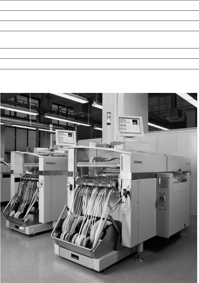
Example of a Placement Line of SIPLACE Compact machines
Description
Flexibility and adaptability cha-
racterize the modular SIPLACE
design. Each production line can
be individually composed of
similar and different modules.
Because of the small size and ro-
bust construction of the SIPLACE
modules, they can be recombined
quickly and easily to accommodate
changes in production requirements.
SIPLACE line-level optimization
tools generate single set-ups for
single products or for several
products. Also, product programs
can be transferred from line to line
even when the machine configura-
tions are different.
The innovative SIPLACE platform,
with its cutting-edge technology,
guarantees maximum productivity,
while compatibility across several
machine generations ensures you
of long-term investment protection.
And with SIPLACE, you benefit
from a global support network with
29 locations in Europe, 32 locations
in the Americas, and 23 locations in
Asia.
Line Design
Technical Data
System SIPLACE SMD placement lines
Modules SIPLACE CS / SIPLACE CF
PCB conveyor Automatic width adjustment
PCB dimensions
(L x W)
50 x 50 mm
2
to 508 x 460 mm
2
/
2" x 2" to 20" x 18"
Placement speed Depends on layout of modules
Space required 4 m² / SIPLACE CS & CF modules
5
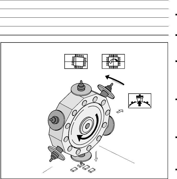
6-Nozzle Collect & Place Head for High Speed Placement
Component Pick-Up/
Placement
Segment
Removal
Point
Turning to
the Placement
Position
Component
Vision
Description
The 6-Nozzle placement head
operates on the Collect & Place
principle. The 6 vacuum nozzles of
the SIPLACE Collect & Place head
rotate around a horizontal axis.
This does not only save space:
Due to the small diameter com-
pared to chip shooters, the cen-
trifugal forces are significantly
lower. The results are high-speed,
reliable placement and the same
cycle time for all components.
Components are picked up and
placed reliably with the aid of vac-
uum followed by a gentle air kiss.
A number of vacuum tests moni-
tors if the component has been
picked up and placed accurately.
Various control and self-learning
functions further enhance the de-
pendability of the system:
The optical recognition of feeder
positions records the exact posi-
tion of the feeder table.
A camera on the placement head
(component vision module) de-
termines the exact position of
each component on the nozzle.
For every feeder the pick-up
offsets are averaged over the
last ten pick-ups. This enables
the head to dial-in on the pre-
cise pick point for each compo-
nent.
In addition, the package form is
also checked. If the actual geo-
metric dimensions of the com-
ponent do not correspond to
those programmed, the compo-
nent is rejected.
Components rejected by the
vision system are dumped into
a bin. Any rejected component
gets automatically placed during
a repair run.
Warpage of the PCB is accom-
modated by sensor stop acti-
vated z-axis placement. The
system also keeps the last ten
positions of the z-axis at com-
ponent placement and uses the
average of these values to im-
prove the drive down and place
speed of the cycle.
Placement Heads:
6-Nozzle Collect & Place Head for High Speed
Component Placement
Technical Data
Benchmark placement rate See table on page 3
Stroke of Z-axis max. 16 mm
Programmable placement force 2.4 to 5.0 N
Accuracy and Component range See table on page 7
6
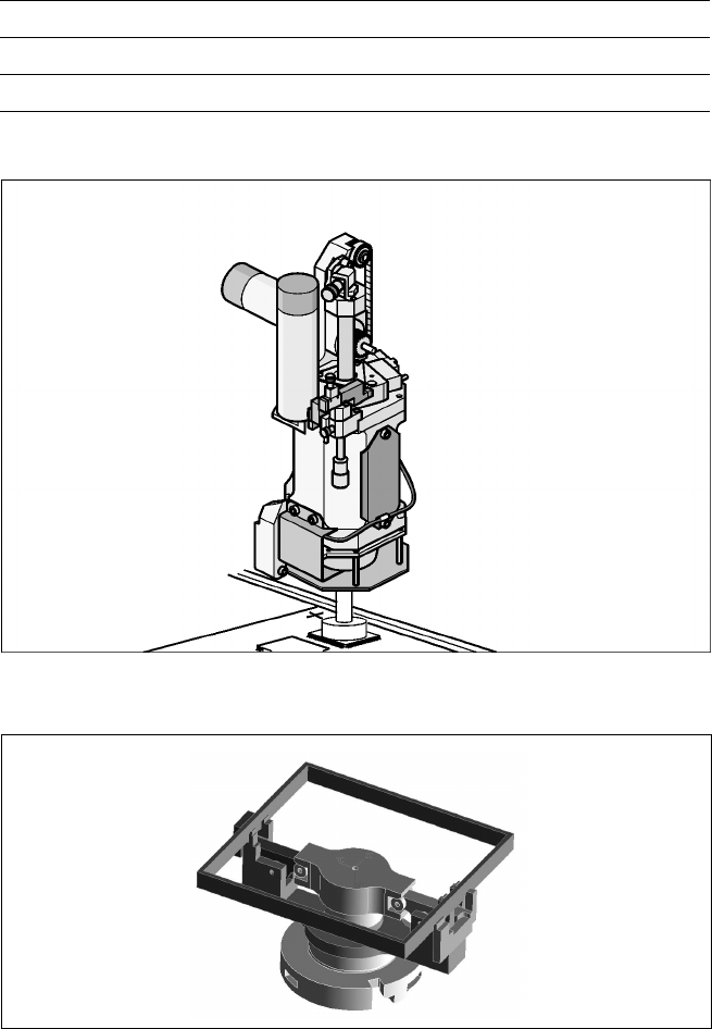
Description
This head operates on the Pick
& Place principle. It is suitable for
picking up particularly sophisti-
cated or large components as well
as non-standard models. High-
resolution and intelligent vision
modules ensure that the compo-
nents meet specified tolerances
and that the placement position
is correct.
The sleeve and nozzle are the
heart of the Pick & Place Head.
The sleeve is mounted such that it
is movable in the longitudinal
(Z-axis) and rotational direction
(D-axis). Each of the two axes are
driven by a DC motor and posi-
tioning is done by incremental en-
coder. Due to the high-resolution
glass incremental panel on the
sleeve, the Pick & Place Head has
an outstanding high rotational posi-
tion accuracy. The movement of
rotation is transmitted directly
from the D-axis motor to the driv-
ing plate on the sleeve via frictional
wheel.
Special nozzles and grippers
increase the component range
of SIPLACE CF. They are either
specific for an individual compo-
nent or for a component family
and suitable for the nozzle
changer. The gripper can even
handle easily components without
a surface for vacuum pick-up.
Placement Heads:
Pick & Place Head for High End / High Accuracy
Component Placement
Technical Data
Benchmark placement rate See table on page 3
Programmable placement force 1 to 10 N
Accuracy and Component range See table on page 7
Pick & Place Head
Gripper with OSC