Specification SIPLACE CF-Medium.pdf - 第23页
22 Desc ription Despit e the highly stable machine frame, slight distor tions of the gentry a xes cannot always be avoid ed. With the aid of the mapp ing process the high place- ment accu racy o f th e ma chine is pres e…

21
Description
Standard Component Vision
Standard Component VisionStandard Component Vision
Standard Component Vision
Module for the 6-Nozzle
Module for the 6-NozzleModule for the 6-Nozzle
Module for the 6-Nozzle
Collect & Place Head
Collect & Place HeadCollect & Place Head
Collect & Place Head
The standard component vision
module is directly integrated into
the Collect & Place Head. While
the component is cycling into the
next station of the Collect & Place
Head, the recorded image is
evaluated by the central vision sys-
tem. The component rotation is
then corrected by the appropriate
angle based on the position off-
sets determined with vision in-
spection.
Standard Component
Standard ComponentStandard Component
Standard Component
Vision Module for the
Vision Module for theVision Module for the
Vision Module for the
Pick & Place Head
Pick & Place HeadPick & Place Head
Pick & Place Head
The Standard Component Vision
Module operates according to a
sophisticated lighting technology
and utilizes diverse analysis algo-
rithms. Despite the great diversity
of components it boasts very high
recognition reliability with all SMD
modules. Like all other vision
modules, this one is also con-
nected to the station’s central
vision system.
The components are illuminated
from four lighting planes whose in-
tensity can be adjusted in 256 in-
crements. This enables an optimal
illumination of each component.
The gray-scale picture recorded is
analyzed using the algorithm best
suited for the package form.
ICs, CSPs and IC-sockets are cen-
tered using leads or bumps. In the
case of chips and odd-shaped
components, centering is based
on outline measurement.
A special inspection mode for the
critical IC lead ends (HALE) pre-
cisely determines the lateral lead
bend as well as pitch error and
lead offset. This greatly reduces
the risk of short circuit soldering
defects.
The rotational angle deviation and
the X-/Y-offset of the component
relative to the nozzle center is as-
certained and factored in during
placement. The X-/Y-offset also
results in the correction of the
pick-up position.
In order to have the vision module
center a component, it must first
be described geometrically in the
package form (GF) file.
The component test software
makes it possible to check the
component definition at the station
to determine whether adjustments,
in lighting for example, are neces-
sary. These adjustments are auto-
matically assigned as a file to the
pertinent package form which
represents a component type.
Hence they are valid for all of
the machines in a line. As the
final step, the GF number of
the component type is entered
in the component file.
Vision Sensor Technology:
Standard Component Vision Modules for the 6-Nozzle
Collect & Place Head
Standard Component Vision Module for the Pick & Place Head
Standard Component Vision Module for the 6-Nozzle Collect & Place Head
Component size
minimum
maximum
0.6 x 0.3 mm
2
(0201)
18.7 x 18.7 mm
2
Component range See table on page 7
Camera’s field of view 24 x 24 mm
2
Illumination
Front light
(3 freely programmable planes)
Pixel size 50 µm
Standard Component Vision Module for the Pick & Place Head
Component size
minimum
maximum
1.6 x 0.9 mm
2
(0603)
32 x 32 mm
2
(single measurement)
55 x 55 mm
2
(multiple measurement)
92 mm edge length
Component range See table on page 7
Camera’s field of view 38 x 38 mm
2
Illumination Front light
(4 freely programmable planes)
Pixel size 80 µm
22
Description
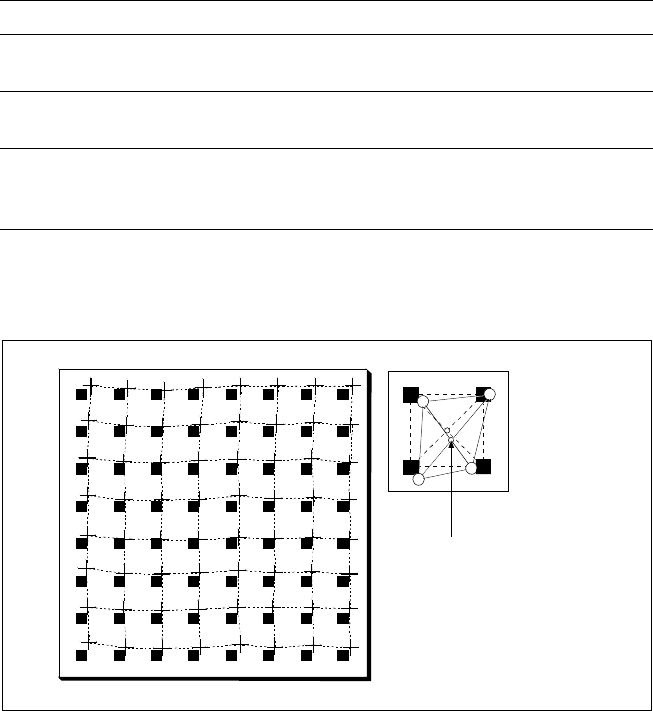
Despite the highly stable machine
frame, slight distortions of the
gentry axes cannot always be
avoided. With the aid of the
mapping process the high place-
ment accuracy of the machine is
preserved throughout its entire
service life.
With this calibrating procedure,
which can be conducted quickly
and easily, the PCB camera recog-
nizes the fiducials on a mapping
calibration plate placed in its oper-
ating area. Any distortions are re-
vealed by comparing the nominal
grid on the glass plate with the
actual grid “drawn” by placement
head. These distortions are taken
into account during all further
positioning of X-/Y-axes and
thus compensated for.
Machine Criteria:
Mapping (Option)
Technical Data
Dimensions of the mapping test plate 520 x 460 mm
2
Number of measurement points
13 x 11 (standard resolution)
26 x 21 (high resolution)
Ambient temperature during calibration
+ 20° ± 3°C
Components of the option
Test plate (special glass)
Calculation data (disk)
Case for secure storage
Nominal Grid of Mapping Plate and Actual Grid with
Deviations Due to Gantry
Corrected
Position
23
Description
Line Programming Sy
Line Programming SyLine Programming Sy
Line Programming Sys
ss
stem
temtem
tem
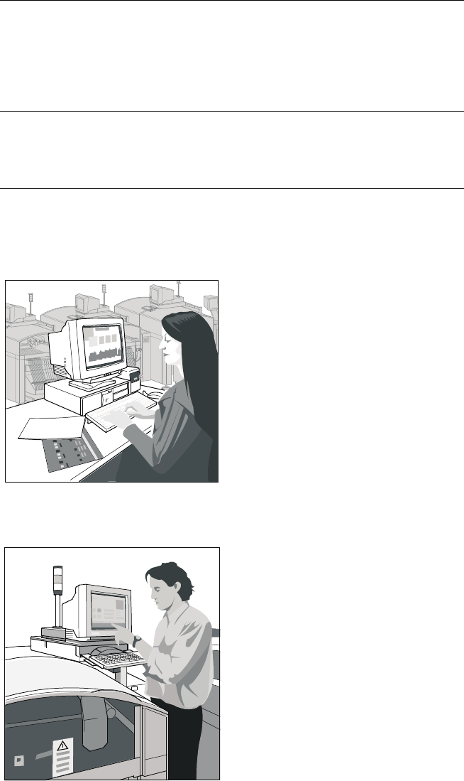
The programming System
SIPLACE C Pro, which runs on
standard PC using Windows XP
operating system, optimizes and
controls complete SIPLACE
placement lines. Consequently
secondary times are reduced and
maximum productivity is guaran-
teed. A graphical user interface
eliminates operating errors.
Station Computer
Station ComputerStation Computer
Station Computer
The station computer in conjunc-
tion with the machine controller
with its realtime capability per-
forms the following jobs: digital
control of the machine gantry
systems; control of PCB input
and output and of PCB transport;
monitoring functions, handling of
malfunctions and output of error
messages (including Help system);
ensuring the optimal quality of the
placement process.
SIPLACE Software Architecture:
Line Programming System
Station Computer
Line Programming System
Station Computer
Functions
Line Programming System for
Software
Data Preparation – Virtual Product Build
Optimization
Line control
Line monitoring
Data management
SIPLACE C Pro (Windows XP)
Station Computer for
Software
Machine control
Machine monitoring
Machine operation
SW 1.01