Specification SIPLACE CF-Medium.pdf - 第5页
4 Exa m ple of a Pl acement Line of SIPLA CE Com pa ct machines Desc ription Flexibilit y and adaptability cha- ract erize the modular SIPLACE design. Each production line ca n be i ndiv idu ally com pose d o f simil ar …

3
Description
SIPLACE CF placement machines
combine Pick & Place Head and
Collect & Place Head to unite high
precision with high speed.
While the PCB is transferring from
the buffer zone to the stationary
population zone, the Collect &
Place Head is already picking up
components.
As soon as the PCB´s exact posi-
tion is determined by the PCB
camera, the Collect & Place Head
will move into the population zone
and perform its placement se-
quence. This step will be repeated
until all components assigned to
the Collect & Place Head are
placed. When the Collect & Place
Head has finished, the Pick &
Place Head begins picking up and
placing the components assigned
to it, until the board is complete.
This award winning SIPLACE
concept has distinct advantages:
Component tapes can be re-
plenished by splicing a new reel
of components to the end of a
depleting reel. This eliminates
machine stoppage due to com-
ponent replenishment.
Stationary, vibration-free feed-
ers ensure a reliable pick-up of
even the smallest components
(e.g., 0201).
Populating a stationary PCB also
prevents components from
shifting during placement.
Automatic width adjustment, auto-
matic nozzle changers, easy chang-
ing of feeder modules or change-
over tables, which can be replaced
within minutes, allow quick changes
of productions.
The following options are available
for the SIPLACE CF:
Additional changeover tables
enables the reduction of job set-
up time increasing machine
utilisation.
Component Bar Code Scanner
used for feeder set-up verifica-
tion.
SIPLACE CF can be ordered in two
standard configurations:
with two Changeover Tables
(SIPLACE CF) or
with one Changeover Table and
one Waffle Pack Changer
(SIPLACE CF/WPW).
Machine Description
Technical Data
Type of placement head
Pick & Place Head and
6-Nozzle Collect & Place Head
Number of gantries 1
Benchmark placement rate
a
1,800 cph (Pick & Place Head)
9,000 cph (6-Nozzle Collect & Place Head)
Component Range 0.6 x 0.3 mm
2
(0201) to 55 x 55 mm
2
Max. placement accuracy
(at 4 sigma)
a
50 µm (Pick & Place Head)
90 µm (6-Nozzle Collect & Place Head)
PCB dimensions
(L x W)
50 x 50 mm
2
to 508 x 460 mm
2
/
2" x 2" to 20" x 18"
Feeding capacity 118 tracks, 8 mm tape
Component table
Quick changeover table with integrated
wheels, reel holder, scrap bin, cutting tool,
SIPLACE Waffle Pack Changer
Types of Feeder modules Tapes, Bulk Cases, Stick Magazines,
Operating system Microsoft Windows / RMOS
Power 1,9 kW
Compr. air requirements 5 - 10 bar, 350 Nl/min, tube ¾"
Standard configuration
Nozzle changer
Feeder package
SMEMA
a) As defined in Scope of Service and Delivery SIPLACE.
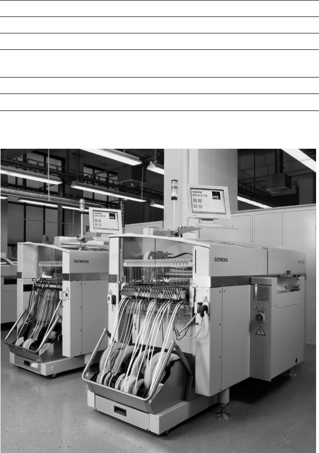
4
Example of a Placement Line of SIPLACE Compact machines
Description
Flexibility and adaptability cha-
racterize the modular SIPLACE
design. Each production line can
be individually composed of
similar and different modules.
Because of the small size and ro-
bust construction of the SIPLACE
modules, they can be recombined
quickly and easily to accommodate
changes in production requirements.
SIPLACE line-level optimization
tools generate single set-ups for
single products or for several
products. Also, product programs
can be transferred from line to line
even when the machine configura-
tions are different.
The innovative SIPLACE platform,
with its cutting-edge technology,
guarantees maximum productivity,
while compatibility across several
machine generations ensures you
of long-term investment protection.
And with SIPLACE, you benefit
from a global support network with
29 locations in Europe, 32 locations
in the Americas, and 23 locations in
Asia.
Line Design
Technical Data
System SIPLACE SMD placement lines
Modules SIPLACE CS / SIPLACE CF
PCB conveyor Automatic width adjustment
PCB dimensions
(L x W)
50 x 50 mm
2
to 508 x 460 mm
2
/
2" x 2" to 20" x 18"
Placement speed Depends on layout of modules
Space required 4 m² / SIPLACE CS & CF modules
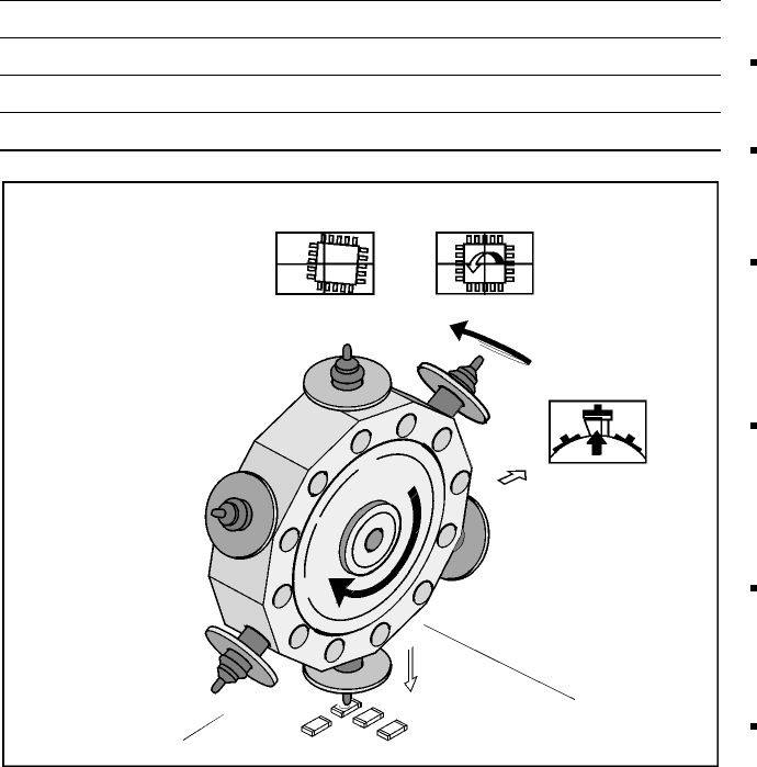
5
6-Nozzle Collect & Place Head for High Speed Placement
Component Pick-Up/
Placement
Segment
Removal
Point
Turning to
the Placement
Position
Component
Vision
Description
The 6-Nozzle placement head
operates on the Collect & Place
principle. The 6 vacuum nozzles of
the SIPLACE Collect & Place head
rotate around a horizontal axis.
This does not only save space:
Due to the small diameter com-
pared to chip shooters, the cen-
trifugal forces are significantly
lower. The results are high-speed,
reliable placement and the same
cycle time for all components.
Components are picked up and
placed reliably with the aid of vac-
uum followed by a gentle air kiss.
A number of vacuum tests moni-
tors if the component has been
picked up and placed accurately.
Various control and self-learning
functions further enhance the de-
pendability of the system:
The optical recognition of feeder
positions records the exact posi-
tion of the feeder table.
A camera on the placement head
(component vision module) de-
termines the exact position of
each component on the nozzle.
For every feeder the pick-up
offsets are averaged over the
last ten pick-ups. This enables
the head to dial-in on the pre-
cise pick point for each compo-
nent.
In addition, the package form is
also checked. If the actual geo-
metric dimensions of the com-
ponent do not correspond to
those programmed, the compo-
nent is rejected.
Components rejected by the
vision system are dumped into
a bin. Any rejected component
gets automatically placed during
a repair run.
Warpage of the PCB is accom-
modated by sensor stop acti-
vated z-axis placement. The
system also keeps the last ten
positions of the z-axis at com-
ponent placement and uses the
average of these values to im-
prove the drive down and place
speed of the cycle.
Placement Heads:
6-Nozzle Collect & Place Head for High Speed
Component Placement
Technical Data
Benchmark placement rate See table on page 3
Stroke of Z-axis max. 16 mm
Programmable placement force 2.4 to 5.0 N
Accuracy and Component range See table on page 7