A10011-ASM-T46-EN-Spec-SX-V2_DMS.pdf - 第15页
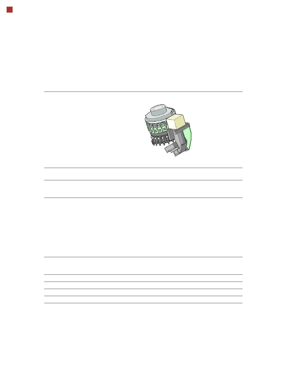
15 Placement heads SIPLACE MultiStar (CPP) SIPLACE MultiStar (CPP) With component camera type 30 With component camera type 33 (stationary camera) Component range a a) Please note that the placeable comp onent range is a…
14
Placement heads
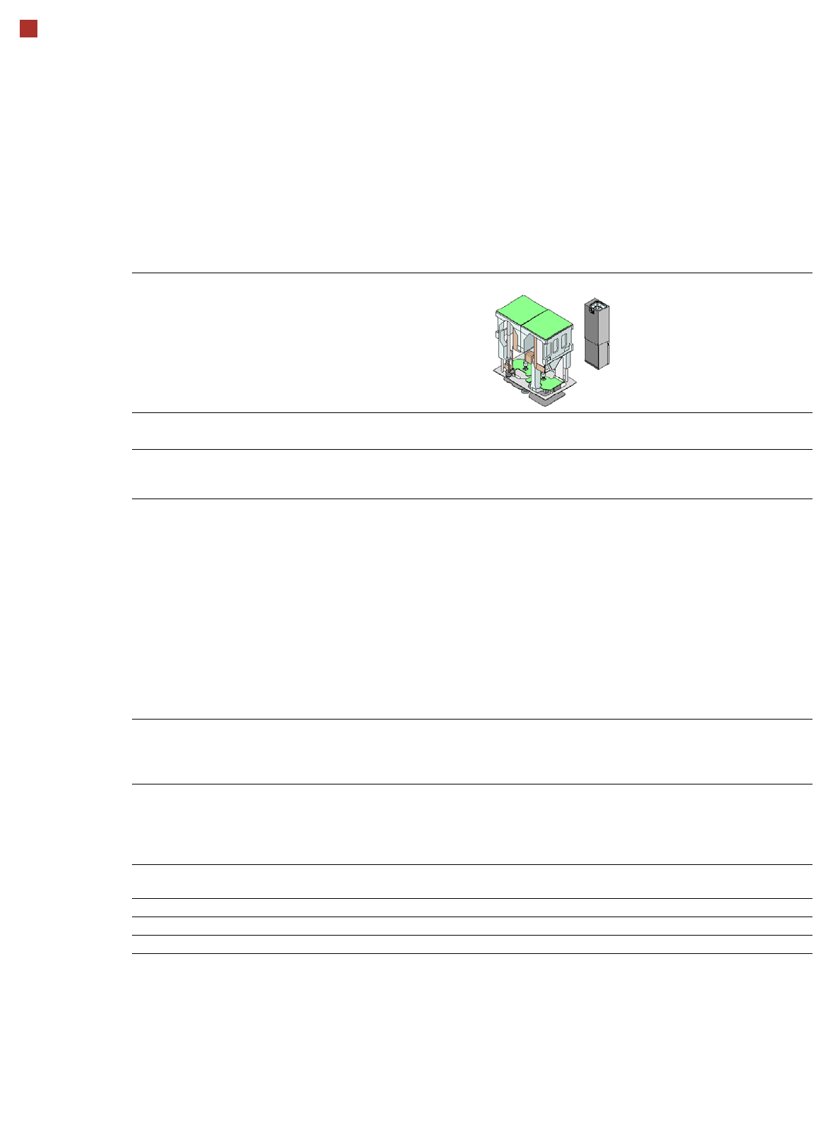
SIPLACE SpeedStar (C&P20 P)
SIPLACE SpeedStar (C&P20 P)
With component camera
type 23
With component camera
type 41
Component range
a
a) Please note that the placeable component range is also affected by the pad geometry, the customer-spe-
cific standards, the component packaging tolerances and the component tolerances.
01005 to 2220, Melf, SOT,
SOD
0201 (metric) to 2220, Melf,
SOT, SOD, Bare-Die, Flip-
Chip
Component spec.
Max. height
Min. lead pitch
Min. lead width
Min. ball pitch
Min. ball diameter
Min. dimensions
Max. dimensions
Max. weight
4 mm
250 µm
100 µm
400 µm
200 µm
0.18 mm x 0.18 mm
6 mm x 6 mm
1 g
4 mm
80 µm
30 µm
100 µm
50 µm
0.12 mm x 0.12 mm
6 mm x 6 mm
1 g
Set-down force 1.3 N ± 0.5 N (default value)
0.5 N - 4.5 N
Touchless Placement
Nozzle types 40xx 40xx
X/Y accuracy
b
b) The accuracy values fulfill the conditions in the SIPLACE scope of supply and services.
± 41µm / 3 ± 41µm / 3
Angular accuracy ± 0.5° / 3 ± 0.5° / 3
Illumination levels 5 5
15
Placement heads
SIPLACE MultiStar (CPP)
SIPLACE MultiStar (CPP)
With component camera
type 30
With component camera type 33
(stationary camera)
Component range
a
a) Please note that the placeable component range is also affected by the pad geometry, the customer-spe-
cific standards, the component packaging tolerances and the component tolerances.
01005 to 27 mm x 27 mm 0402 to 50 mm x 40 mm
b
b) A diagonal of 69 mm is possible during multiple measurements (e.g. 64 mm x 10 mm).
Component spec.
Max height
c
Max. height
d
Min. lead pitch
Min. lead width
Min. ball pitch
Min. ball diameter
Min. dimensions
Max. dimensions
Max. weight
c) CPP head: in low installation position (stationary component camera not possible).
d) CPP head: In high installation position
6.0 mm
8.5 mm
250 µm
100 µm
e
/ 200 µm
f
250 µm
e
/ 350 µm
f
140 µm
e
/ 200 µm
f
0.4 mm x 0.2 mm
27 mm x 27 mm
4 g
g
e) For components < 18 mm x 18 mm.
f) For components ≥ 18 mm x18 mm.
g) 20 g in „Pick&Place“ mode
11.5 mm / 15.5 mm
h
300 µm
150 µm
350 µm
200 µm
1.0 mm x 0.5 mm
50 mm x 40 mm
8 g
g
Set-down force 1.0 - 15 N
h
h) With OSC package
Nozzle types 20xx, 28xx 20xx, 28xx
X/Y accuracy
i
i) The accuracy values fulfill the conditions in the SIPLACE scope of supply and services.
± 38 µm/3 ± 30 µm/3
Angular accuracy ± 0.20° / 3
j
, ± 0.38° / 3
k
j) Component dimensions between 6 mm x 6 mm and 27 mm x 27 mm.
k) Component dimensions smaller than 6 mm x 6 mm.
± 0.12° / 3
Illumination levels 5 6
16
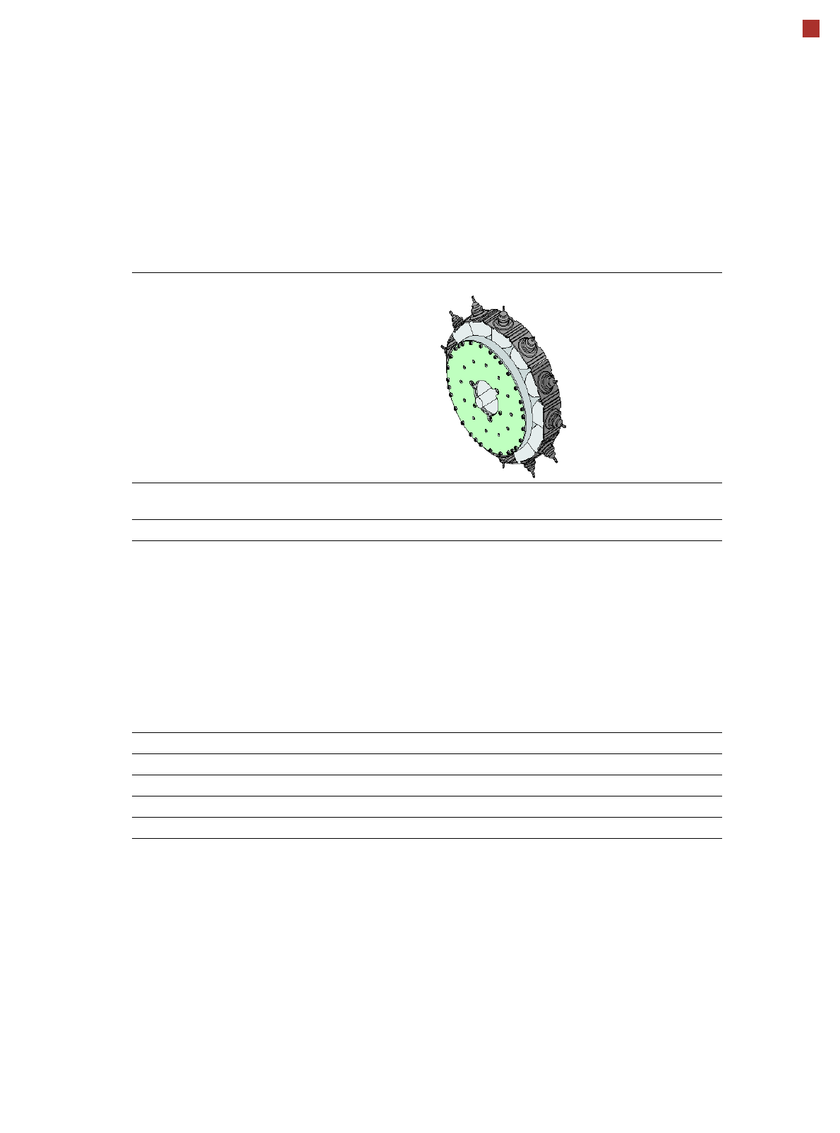
Placement heads
SIPLACE TwinStar (TH)
SIPLACE TwinStar (TH)
With component camera type 33
(fine pitch camera)
With component camera type 25
(flip chip camera)
Component range
a
a) Please note that the placeable component range is also affected by the pad geometry, the customer-specific standards, the
component packaging tolerances and the component tolerances.
0402 to SO, PLCC, QFP, BGA, special
components, bare dies, flip-chips
0201 to SO, PLCC, QFP, sockets, plugs,
BGA, special components, bare dies, flip-
chips, shields
Component specs
Max. height
Min. lead pitch
Min. lead width
Min. ball pitch
Min. ball diameter
Min. dimensions
Max. dimensions
Max. weight
b
b) Component plus nozzle or gripper.
25 mm / 50 mm
c
300 µm
150 µm
350 µm
200 µm
1.0 mm x 0.5 mm
55 mm x 45 mm (single measurement)
Up to
200 mm x 125 mm (multiple measurement)
d
100 g to 240 g
e
c) Only with SIPLACE Very High Force Twin Star (VHF TH)
d) Further restrictions will apply, according to the component dimensions and the component supply. These will be automati-
cally taken into account by SIPLACE Pro.
e) Up to 100 g is standard. Over 100 g available with reduced acceleration. From 160 g only with SIPLACE Very High Force
Twin Star (VHF TH)
25 mm / 40 mm
c
250 µm
100 µm
140 µm
80 µm
0.6 mm x 0.3 mm
16 mm x 16 mm (single measurement)
Up to
55 mm x 55 mm (multiple measurement)
d
100 g to 240 g
e
Set-down force 1.0 N - 15 N
1.0 N - 30 N with OSC package
2.0 N - 70 N
c
2.0 N -100 N
f
f) Only with SIPLACE Very High Force Twin Star (VHF TH) and OSC package
1.0 N - 15 N
1.0 N - 30 N with OSC package
2.0 N - 70 N
c
2.0 N -100 N
f
Nozzle types
g
g) Over 300 different nozzles and 100 gripper types are available, with an extensive nozzle database available online.
5xx (standard)
20xx/28xx + adapter
4xx + adapter
9xx + adapter
Gripper
5xx (standard)
20xx/28xx + adapter
4xx + adapter
9xx + adapter
Gripper
Nozzle spacing for P&P
heads
70.8 mm 70.8 mm
X/Y accuracy
h
h) The accuracy values fulfill the conditions in the SIPLACE scope of supply and services.
± 26 µm/3 ± 22 µm/3
Angular accuracy ± 0.05° / 3 ± 0.05° / 3
Illumination levels 6 6