A10011-ASM-T46-EN-Spec-SX-V2_DMS.pdf - 第23页
23 PCB warpage PCB warpage across the direction of travel max. 1 % of the PCB diagonal, but not exceeding 2 mm PCB warpage on the conveyor Fixed clamped edge Movable clamping device PCB Fixed clamped edge Conveyor belt P…
22
Board conveyor
I-Placement
Alternating placement mode
Alternating placement or
I-Placement mode
Distance of outer conveyor
edges: 562 mm, 2 lanes, outer
conveyor edges fixed
Alternating placement mode
Distance of outer conveyor
edges: 562 mm, 2 lanes, right
conveyor edges fixed
a
Alternating placement mode
Distance of outer conveyor
edges: 560 mm, dual conveyor
in single conveyor mode, right
conveyor edge fixed
a
Max. 260
Movable conveyor side
Stationary conveyor side
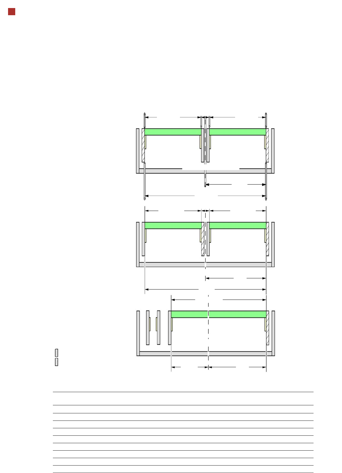
a) The diagram only shows settings with a fixed righthand conveyor edge. A setting with the stationary conveyor
edge on the left is also possible. All dimensions in millimeters.
Max. 260
281
562
Min. 35
281
179
Max. 260
281
Min. 35
Max. 260
562
Max. 460
Machine center
Machine center
Machine center
Adjustable conveyor side position and max. PCB width
Conveyor side position Max. PCB width Distance of fixed sides to one another, for various fixed side
position settings
Outside Right or left
234.2 mm 216 mm 468.4 mm 251.7 mm
254 mm 236 mm 508 mm 272 mm
259.7 mm 242 mm 519.4 mm 277.2 mm
268 mm 250 mm 536 mm 286 mm
268 mm SMEMA 250 mm 536 mm 285.5 mm
281 mm 260 mm 562 mm 299 mm
281 mm SMEMA 260 mm 562 mm 298.5 mm
Customized max. 260 mm max. 562 mm max. 299 mm
23
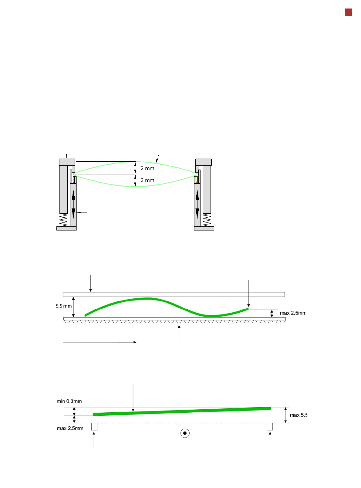
PCB warpage
PCB warpage across the direction of travel
max. 1 % of the PCB diagonal, but not
exceeding 2 mm
PCB warpage on the conveyor
Fixed clamped edge
Movable clamping device
PCB
Fixed clamped edge
Conveyor belt
PCB transport direction
Front board edge
Front board edge
PCB warpage in direction of travel + PCB thickness < 5.5 mm
Bending up of front board edge max. 2.5 mm
Left conveyor belt
Right conveyor belt
PCB transport direction
24
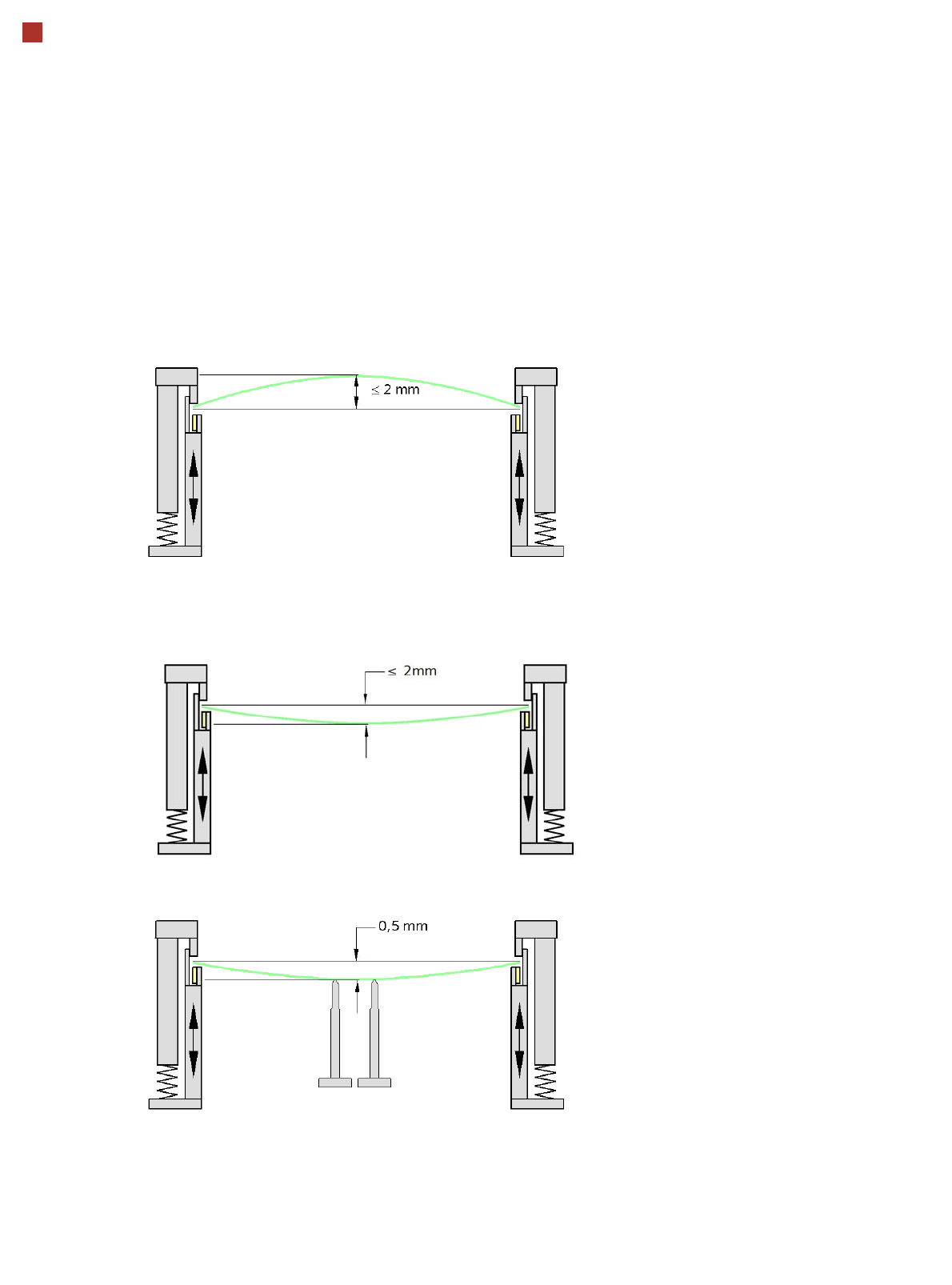
PCB warpage
PCB warpage during placement
To avoid impairing the placement quality and
speed, we recommend using a PCB support e.g.
Smart Pin Support so that the PCB warpage
downwards does not exceed 0.5 mm.
PCB warpage up, max. 2 mm
PCB support
PCB warpage down, max. 2 mm
Changes in the surface position are automatically applied by the functions for learning the height.