Galaxy EX Machine Control.pdf - 第11页
MACHINE CO NTROL M36 MACHINE CONTROL E N CLOSURE Ch apte r Issue 4, Jun 18 Tech nical Ref erenc e Ma nual 8.11 Ne xt M ove In te rf ac e Edge Co nn ector The e dge co nnector con nects the ca r d to the b ackplane of the…
MACHINE CONTROL
M36 MACHINE CONTROL ENCLOSURE
8.10 Technical Reference Manual Chapter Issue 4, Jun 18
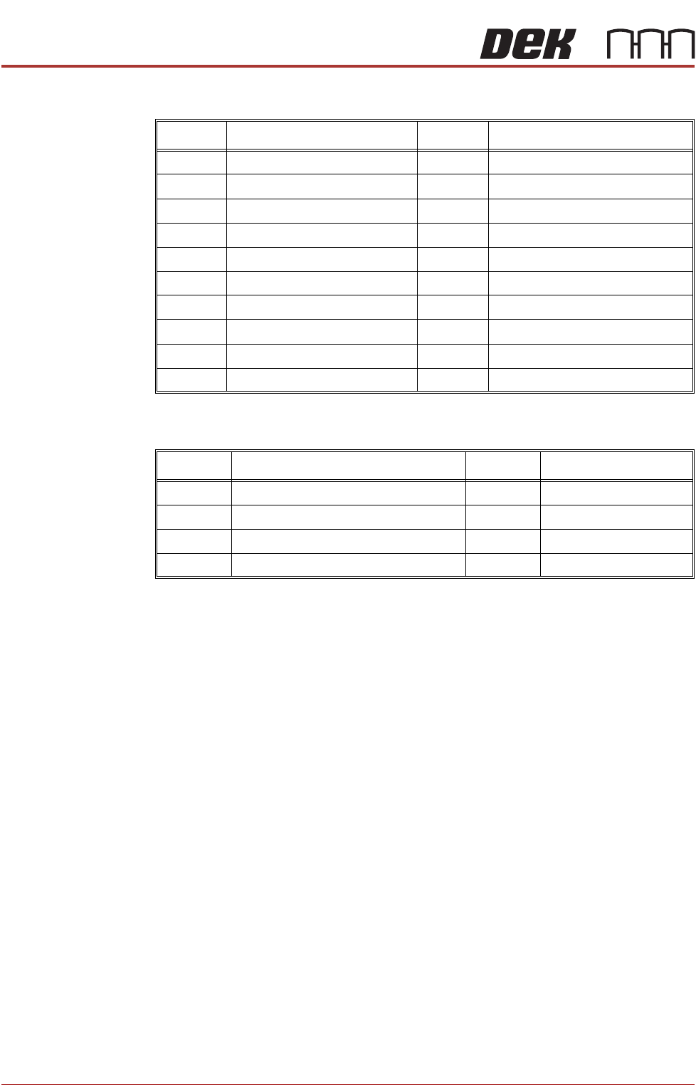
Inputs The table below details the 20 digital inputs:
Outputs The table below details the 8 digital outputs:
Input Function Input Function
DIG IN 0 Spare DIG IN 10 Board at Left
DIG IN 1 Camera X Home DIG IN 11 Board at Right
DIG IN 2 Camera Y Home DIG IN 12 Jog Left
DIG IN 3 Front Squeegee Home DIG IN 13 Jog Right
DIG IN 4 Rear Squeegee Home DIG IN 14 Power ‘ON’ Monitor
DIG IN 5 Moving Rail Home DIG IN 15 Cover Interlock
DIG IN 6 Rail Lifted - Left DIG IN 16 Upline Ready
DIG IN 7 Rail Lifted - Right DIG IN 17 Downline Ready
DIG IN 8 Board at Stop DIG IN 18 Board Pass I/P
DIG IN 9 Board Stop Extended DIG IN 19 Spare
Output Function Output Function
DIG OUT 1 Trigger Image Capture DIG OUT 5 Send Upline
DIG OUT 2 Belt Motors Start-Stop DIG OUT 6 Send Downline
DIG OUT 3 Belt Motors Direction DIG OUT 7 Board Pass O/P
DIG OUT 4 Spare Error Out Software E Stop Power
MACHINE CONTROL
M36 MACHINE CONTROL ENCLOSURE
Chapter Issue 4, Jun 18 Technical Reference Manual 8.11
NextMove Interface
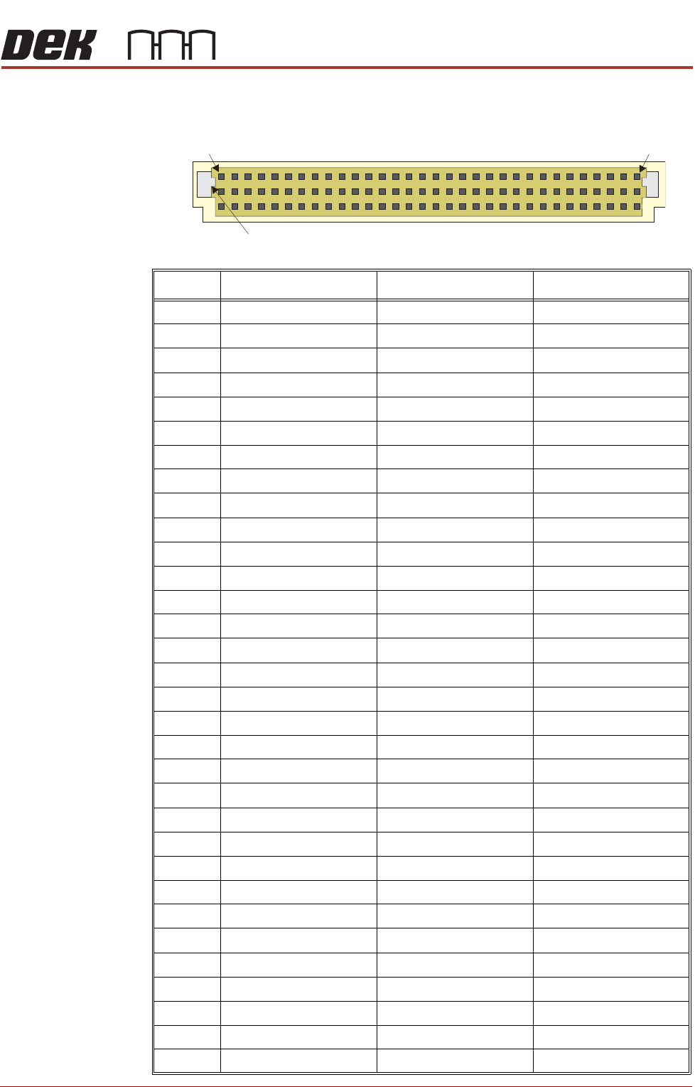
Edge Connector
The edge connector connects the card to the backplane of the enclosure.
Pin No. Row a Row b Row c
1 24V US 24V US N/C
2 24V SW 24V SW N/C
3 N/C N/C Error Out (NextMove)
4 DIN0 (NextMove) DIN0 (Machine) DOUT1 (NextMove)
5 DIN1 (NextMove) DIN1 (Machine) DOUT2 (NextMove)
6 DIN2 (NextMove) DIN2 (Machine) DOUT3 (NextMove)
7 DIN3 (NextMove) DIN3 (Machine) DOUT4 (NextMove)
8 DIN4 (NextMove) DIN4 (Machine) DOUT5 (NextMove)
9 DIN5 (NextMove) DIN5 (Machine) DOUT6 (NextMove)
10 DIN6 (NextMove) DIN6 (Machine) DOUT7 (NextMove)
11 DIN7 (NextMove) DIN7 (Machine) N/C
12 DIN8 (NextMove) DIN8 (Machine) +12V
13 DIN9 (NextMove) DIN9 (Machine) N/C
14 DIN10 (NextMove) DIN10 (Machine) -12V
15 DIN11 (NextMove) DIN11 (Machine) N/C
16 DIN12 (NextMove) DIN12 (Machine) +5.5V
17 DIN13 (NextMove) DIN13 (Machine) N/C
18 DIN14 (NextMove) DIN14 (Machine) DGND
19 DIN15 (NextMove) DIN15 (Machine) N/C
20 DIN16 (NextMove) DIN16 (Machine) N/C
21 DIN17 (NextMove) DIN17 (Machine) N/C
22 DIN18 (NextMove) DIN18 (Machine) N/C
23 DIN19 (NextMove) DIN19 (Machine) N/C
24 N/C N/C N/C
25 0V (24V US Return) 0V (24V US Return) N/C
26 0V (24V SW Return) 0V (24V SW Return) N/C
27 N/C E Stop Supply DOUT4 (Machine)
28 N/C DOUT1 (Machine) DOUT5 (Machine)
29 N/C DOUT2 (Machine) DOUT6 (Machine)
30 !DOUT3 (Machine) DOUT3 (Machine) DOUT7 (Machine)
31 N/C N/C N/C
32 N/C N/C N/C
a
b
c
1 32
Keyway
MACHINE CONTROL
M36 MACHINE CONTROL ENCLOSURE
8.12 Technical Reference Manual Chapter Issue 4, Jun 18
Dual Stepper Drive Card
CAUTION
ANTI-STATIC HANDLING. STANDARD PRECAUTIONS MUST BE ADHERED TO
WHEN HANDLING ELECTRONIC CARDS AND CONFIGURING AND INSERTING
INTO THE ENCLOSURES.
The dual stepper drive card consists of two identical stepper motor drive
circuits used to drive two stepper motors.
The card is connected to both the +24V SW and +24V US supplies. The
switched (SW) supply is protected by a diode-fuse transient suppressor circuit.
The diode operates over an extremely short time period, enabling the circuit to
absorb voltage spikes without rupturing the fuse (F1 - 4Amp). If a sustained
voltage is experienced above its rating, the fuse ruptures. The +24V US is
used to produce an internally regulated +5.5V (VCC and VDD).
Whilst the stepper motor is stationary, the card switches to half power to
minimize power consumption.