Galaxy EX Machine Control.pdf - 第32页
MACHINE CONTROL CAN BUS 8.3 2 Tech ni cal Ref ere nce Ma nual Cha pter I ssue 4, Jun 18 I/O Node 1 I/O Node 1 is t he C AN m aste r a nd is also k now n as the N extM ove ES c ard hous ed in th e M3 6 Mach ine Co ntro l …
MACHINE CONTROL
CAN BUS
Chapter Issue 4, Jun 18 Technical Reference Manual 8.31
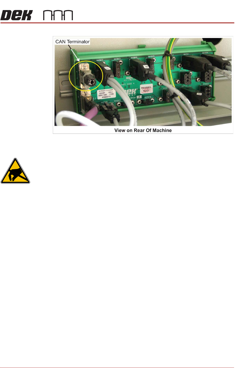
Figure 8-10 CAN Terminator Connection
I/O Node Boards
CAUTION
ANTI-STATIC HANDLING. STANDARD PRECAUTIONS MUST BE ADHERED TO
WHEN HANDLING ELECTRONIC CARDS AND CONFIGURING AND INSERTING
INTO THE ENCLOSURES.
The I/O Node Boards consists of multiple inputs and outputs, CAN encoder/
decoder and multi-way connectors for machine components.
There are three I/O Node Boards fitted to a standard machine with a possible
one other board for the underscreen cleaner, if fitted, these are:
• I/O Node 1 - NextMove ES card (CAN master) located in the M36 Machine
Control Enclosure (standard)
• I/O Node 2 - Main Machine I/O board located at the rear of the machine
(standard)
• I/O Node 3 - Print Carriage I/O board located inside the print carriage
extrusion (standard)
• I/O Node 4 - Screen Cleaner I/O board located at the rear of the machine
(optional)
• I/O Node 5 - OTS/HTC I/O board located at the rear of the machine
(optional)
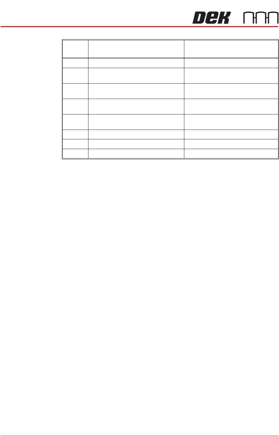
I/O Nodes 2 & 4 have a green (status) and a red (error) LED mounted on the
board. The status LED should flash twice periodically and the error LED
should not be illuminated during normal operation. The following table
describes other operations of the LEDs:
MACHINE CONTROL
CAN BUS
8.32 Technical Reference Manual Chapter Issue 4, Jun 18
I/O Node 1 I/O Node 1 is the CAN master and is also known as the NextMove ES card
housed in the M36 Machine Control Enclosure. For more information, refer to
the M36 Machine Control Enclosure - NextMove ES Card section of this
chapter.
No of
Pulses
Red (error) LED Green (status) LED
Static Off No error Initialisation/Code execution stopped
1 Node ID from DIP switches is 0 CANopen NMT state is ‘pre-opera-
tional’
2 EEPROM contents invalid (EEPROM
empty/checksum error)
CANopen NMT state is ‘operational’
3 EEPROM access impossible (hardware
error)
CANopen NMT state is ‘stopped’
4 CAN controller switched to ‘bus-off’
mode
N/A
5 Firmware error N/A
6 Controller overload N/A
Static On Severe hardware/software error N/A
MACHINE CONTROL
CAN BUS
Chapter Issue 4, Jun 18 Technical Reference Manual 8.33
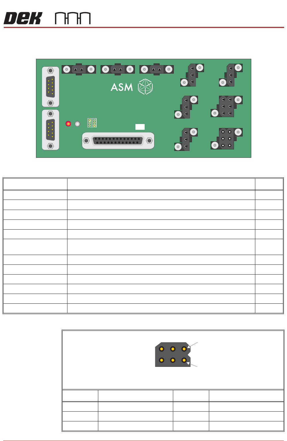
I/O Node 2 (Main Machine I/O)
N2PL1
Connector Description I/O
N2PL1 Power Input
N2PL2 CAN Signal In Input
N2PL3 CAN Signal Out Output
N2SK2 Vacuum Tooling Power/Grid-Lok Tooling Output
N2SK3 Tricolour Beacon Output
N2SK4 Chase Clamps - Screen Clamps - Board Clamps - Board Stop - Lid Bolt - Rail
Board Stop - Cleaner Squeegee - Solvent Tank Pressure
Output
N2SK5 Rising Table Brake Output
N2SK6 Internal Light Output
N2SK7 Air Pressure Sensor Input
N2SK8 Lid Bolt Extended Sensor Input
N2SK9 Vacuum Tooling Sensor Input
N2SK10 Screen Sensor Input
Pin No.SignalPin No.Signal
1 24V US 4 0V
2 0V 5 12V
3 24V SW 6 0V
4
1
6 Way Trident Connector
(with pins)