Galaxy EX Machine Control.pdf - 第13页
MACHINE CO NTROL M36 MACHINE CONTROL E N CLOSURE Ch apte r Issue 4, Jun 18 Tech nical Ref erenc e Ma nual 8.13 Dipswit ch Settin g s Use t he foll owing graph i c and table s to d ete rmine the correct dipswitch se tting…

MACHINE CONTROL
M36 MACHINE CONTROL ENCLOSURE
8.12 Technical Reference Manual Chapter Issue 4, Jun 18
Dual Stepper Drive Card
CAUTION
ANTI-STATIC HANDLING. STANDARD PRECAUTIONS MUST BE ADHERED TO
WHEN HANDLING ELECTRONIC CARDS AND CONFIGURING AND INSERTING
INTO THE ENCLOSURES.
The dual stepper drive card consists of two identical stepper motor drive
circuits used to drive two stepper motors.
The card is connected to both the +24V SW and +24V US supplies. The
switched (SW) supply is protected by a diode-fuse transient suppressor circuit.
The diode operates over an extremely short time period, enabling the circuit to
absorb voltage spikes without rupturing the fuse (F1 - 4Amp). If a sustained
voltage is experienced above its rating, the fuse ruptures. The +24V US is
used to produce an internally regulated +5.5V (VCC and VDD).
Whilst the stepper motor is stationary, the card switches to half power to
minimize power consumption.
MACHINE CONTROL
M36 MACHINE CONTROL ENCLOSURE
Chapter Issue 4, Jun 18 Technical Reference Manual 8.13
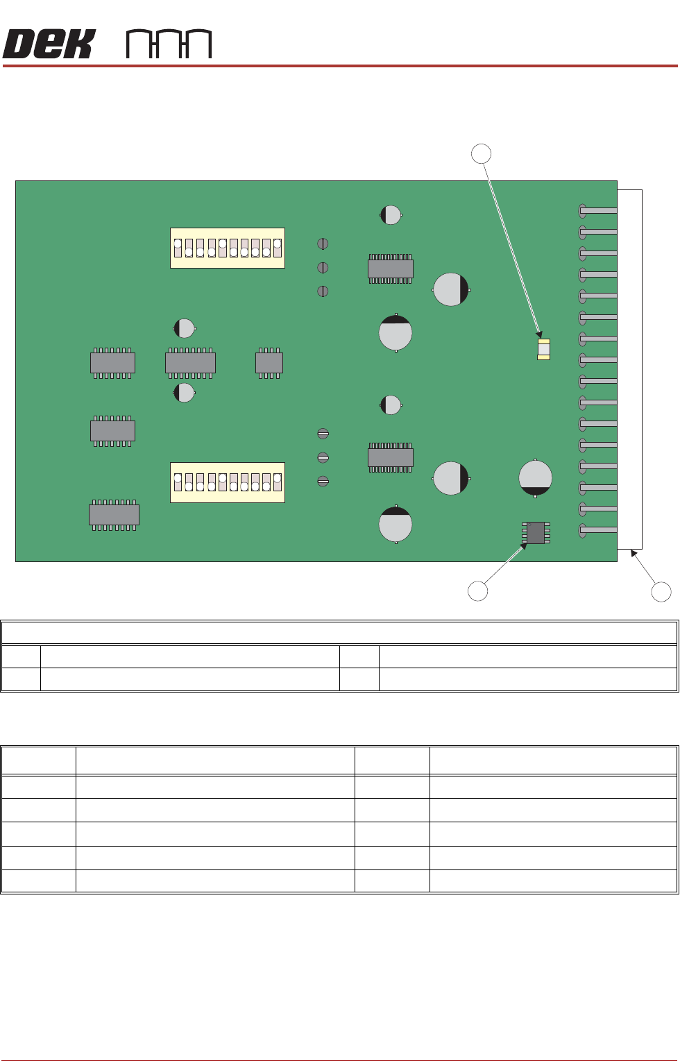
Dipswitch Settings Use the following graphic and tables to determine the correct dipswitch settings:
Each channel has a separate dipswitch which enables various circuit functions
and are shown in the table below:
Dual Stepper Drive Card
1 4A Diode Fuse F1 3 + 5.5V Regulator
2 Edge Connector
Dipswitch Function
Dipswitch Function
1 Enables Full/Half/Quarter/Eighth Step Operation 6 Sets Motor Current Output
2 Enables Full/Half/Quarter/Eighth Step Operation 7 Sets Motor Current Output
3 Half Power Timer Enable 8 Sets Motor Current Output
4 INV_STEP 9 Percent Fast Decay_0
5 INV_DIR 10 Percent Fast Decay_1
MACHINE CONTROL
M36 MACHINE CONTROL ENCLOSURE
8.14 Technical Reference Manual Chapter Issue 4, Jun 18
Stepper Drive Card
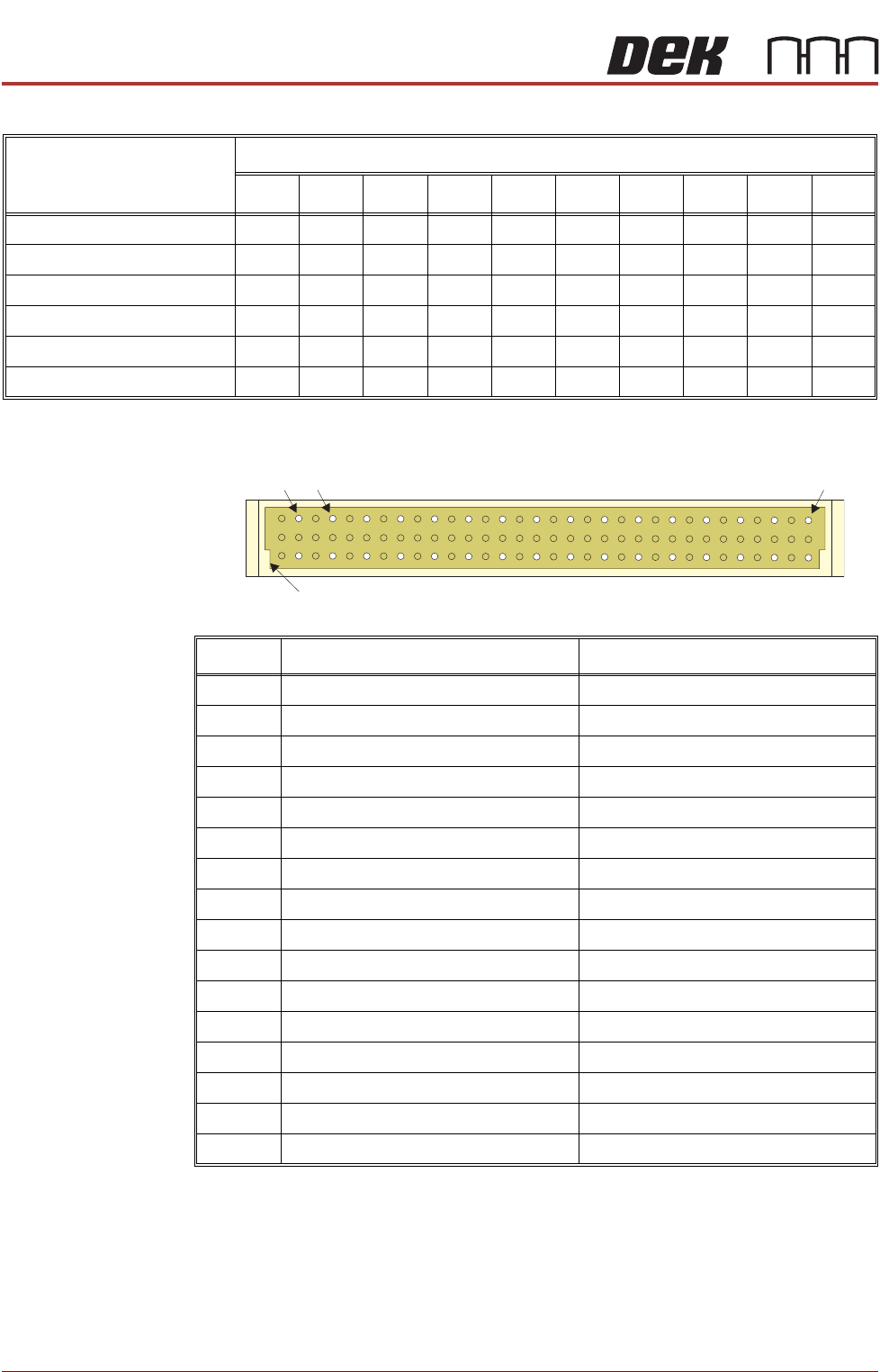
Edge Connector
The edge connector connects the card to the backplane of the enclosure.
Card Position and
Dipswitch
Switch Positions
12345678910
Slot X1 - SW 1 OFF ON ON ON ON OFF ON OFF ON OFF
Slot X1 - SW 2 OFF ON ON ON ON OFF ON OFF ON OFF
Slot X2 - SW 1 OFF ON ON ON ON OFF ON ON ON OFF
Slot X2 - SW 2 OFF ON ON ON ON OFF ON ON ON OFF
Slot X3 - SW 1 OFF ON ON ON ON OFF ON OFF ON OFF
Slot X3 - SW 2 OFF ON ON ON ON OFF ON ON ON OFF
Pin No. Row a Row c
2 CH1 B- CH2 B-
4 CH1 B+ CH2 B+
6 CH1 A- CH2 A-
8 CH1 A+ CH2 A+
10 24V SW 24V SW
12 24V US 24V SW
14 24V US 24V SW
16 GND GND
18 GND GND
20 N/C N/C
22 N/C N/C
24 IDAT ICLK
26 IVPP DIR1
28 VCC OUT STEP1
30 DIR2 STEP2
32 N/C N/C
a
c
2 32
Keyway
4