Galaxy EX Machine Control.pdf - 第14页
MACHINE CONTROL M36 MACHINE CONTROL E N CLOSURE 8.1 4 Tech ni cal Ref ere nce Ma nual Cha pter I ssue 4, Jun 18 Step per D rive Ca rd Edge Co nn ector The e dge co nnector con nects the ca r d to the b ackplane of the en…
MACHINE CONTROL
M36 MACHINE CONTROL ENCLOSURE
Chapter Issue 4, Jun 18 Technical Reference Manual 8.13
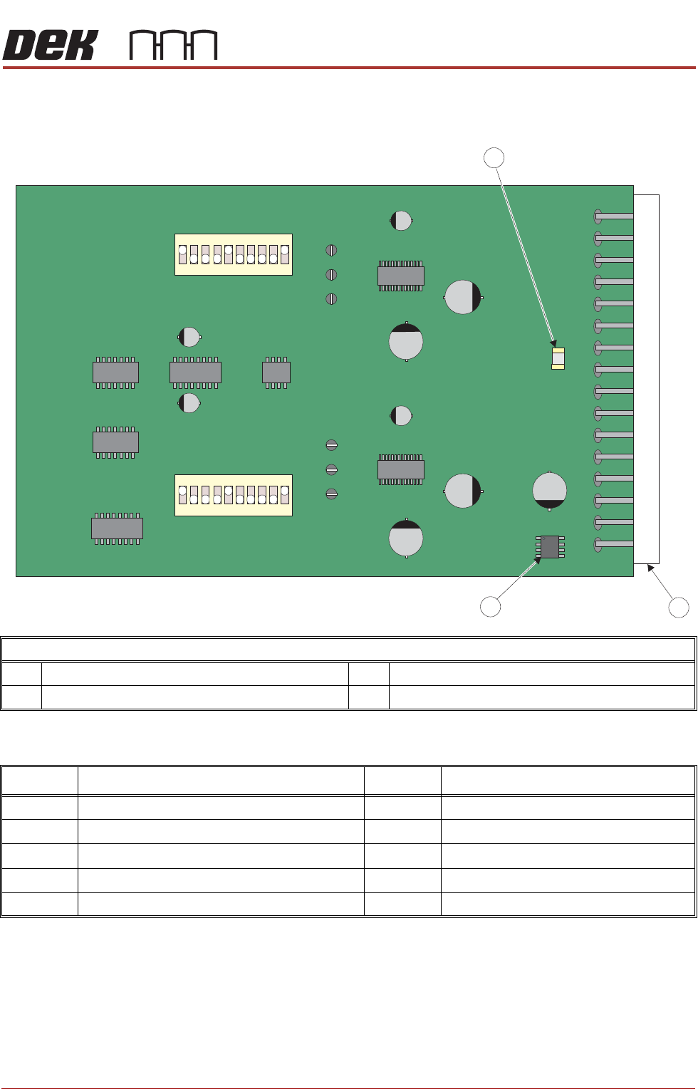
Dipswitch Settings Use the following graphic and tables to determine the correct dipswitch settings:
Each channel has a separate dipswitch which enables various circuit functions
and are shown in the table below:
Dual Stepper Drive Card
1 4A Diode Fuse F1 3 + 5.5V Regulator
2 Edge Connector
Dipswitch Function
Dipswitch Function
1 Enables Full/Half/Quarter/Eighth Step Operation 6 Sets Motor Current Output
2 Enables Full/Half/Quarter/Eighth Step Operation 7 Sets Motor Current Output
3 Half Power Timer Enable 8 Sets Motor Current Output
4 INV_STEP 9 Percent Fast Decay_0
5 INV_DIR 10 Percent Fast Decay_1
MACHINE CONTROL
M36 MACHINE CONTROL ENCLOSURE
8.14 Technical Reference Manual Chapter Issue 4, Jun 18
Stepper Drive Card
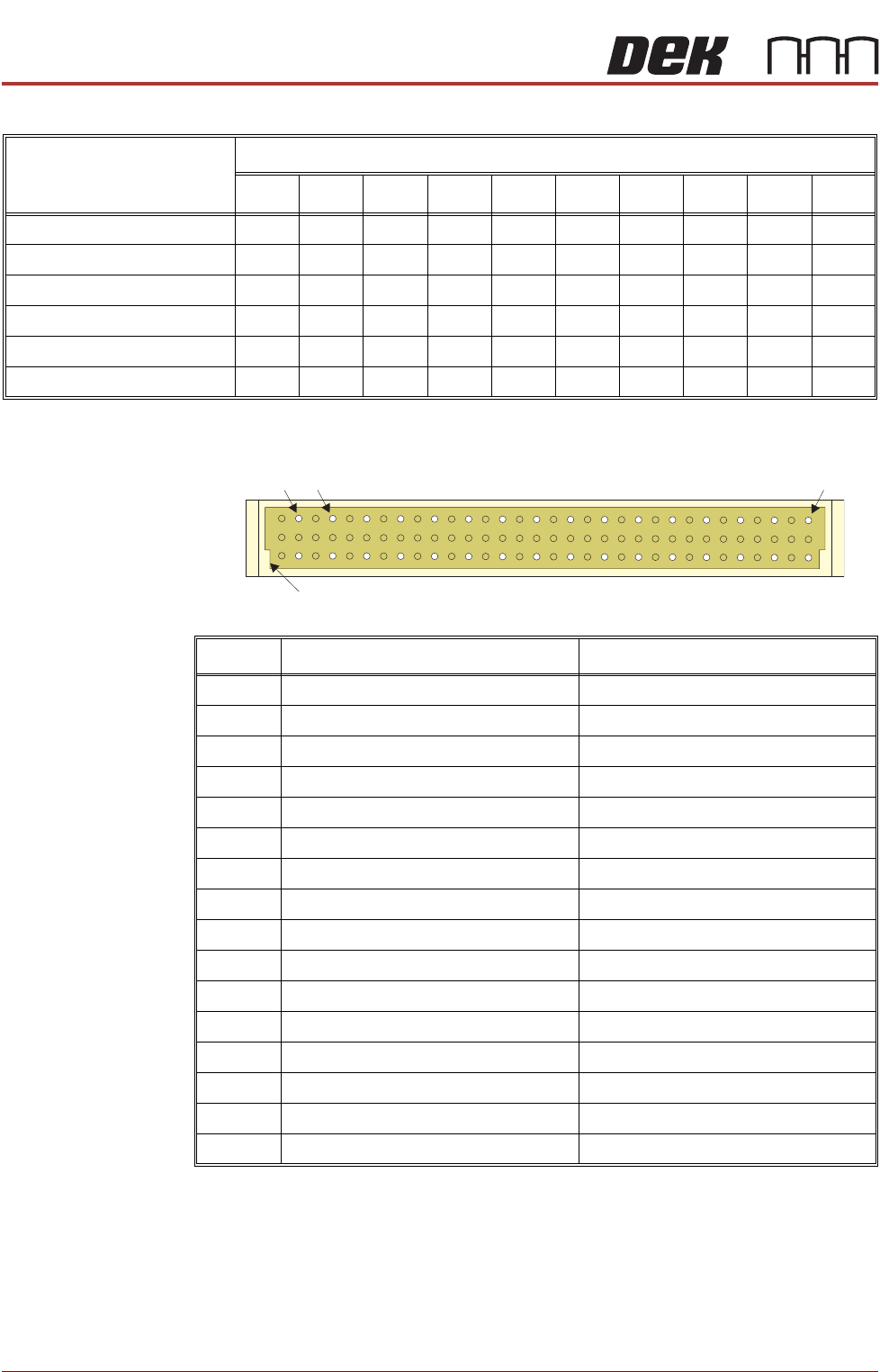
Edge Connector
The edge connector connects the card to the backplane of the enclosure.
Card Position and
Dipswitch
Switch Positions
12345678910
Slot X1 - SW 1 OFF ON ON ON ON OFF ON OFF ON OFF
Slot X1 - SW 2 OFF ON ON ON ON OFF ON OFF ON OFF
Slot X2 - SW 1 OFF ON ON ON ON OFF ON ON ON OFF
Slot X2 - SW 2 OFF ON ON ON ON OFF ON ON ON OFF
Slot X3 - SW 1 OFF ON ON ON ON OFF ON OFF ON OFF
Slot X3 - SW 2 OFF ON ON ON ON OFF ON ON ON OFF
Pin No. Row a Row c
2 CH1 B- CH2 B-
4 CH1 B+ CH2 B+
6 CH1 A- CH2 A-
8 CH1 A+ CH2 A+
10 24V SW 24V SW
12 24V US 24V SW
14 24V US 24V SW
16 GND GND
18 GND GND
20 N/C N/C
22 N/C N/C
24 IDAT ICLK
26 IVPP DIR1
28 VCC OUT STEP1
30 DIR2 STEP2
32 N/C N/C
a
c
2 32
Keyway
4
MACHINE CONTROL
M36 MACHINE CONTROL ENCLOSURE
Chapter Issue 4, Jun 18 Technical Reference Manual 8.15
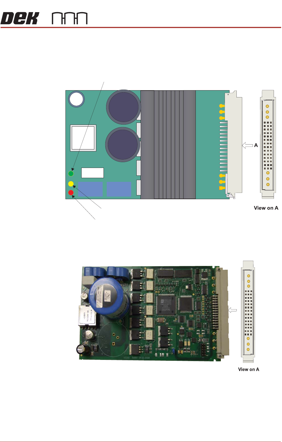
Servo Drive Card Two servo drive cards are used by the machine controller to drive the camera
X and Y axis motors. The axes for these motors are designated Axis 0 and 1.
There are two types of card available and either card type can be fitted.
Figure 8-6 Servo Drive Card (Part Number - 183732)
Figure 8-7 Servo Drive Card (Part Number - 198264)
C1 B1 A1
Power LED
Disable LED
Error LED
A