00193796-06.pdf - 第11页
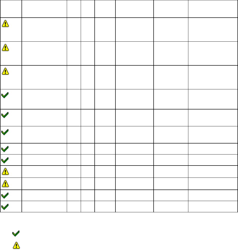
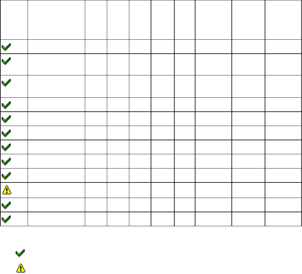
Installation Manual, Station Software Version 505.03 SP1 Edition 08/2005 11 of 154 3.1.3.2 Embedded software for S-25 HM , S-27 HM, HS-50, HS-50+, HS-60 Subsystem HS-50 S-25 HM HS-60 S-27 HM BIOS File name Application 1 …
Installation Manual Station Software Version 505.03 SP1
10 of 154
3.1.3 Minimum requirement for embedded software
3.1.3.1 Embedded software for HF and HF/3
Subsystem HF HF/3 BIOS File name Application 1
Application 2
File name
Main axes X X 2.0 A0300200.bhx 1.03
2.39
A0310103.bhx
X0320239.bhx
Y0320239.bhx
Revolver head axes X X 2.0 A0300200.bhx 1.03
2.39
A0310103.bhx
X0320239.bhx
Y0320239.bhx
Twin head Z axis X X 2.0 A0300200.bhx 1.03
2.39
A0310103.bhx
P0320239.bhx
R0320239.bhx
Twin head dp axis X X 2.0 A0300200.bhx 1.03
2.30
A0310103.bhx
A0320230.bhx
Revolver head
functions
X X 1.04
3C8
K0400104.hex
K06003C8.bhx
6.09
1.0C
K0410609.hex (8 bit)
K061010C.hex (16 bit)
Twin head functions X X 3C8 I01003C8.bhx 2.05 I0110205.bhx
I0310205.bhx
Component table X X 1.01 B0200101.hex 1.04 B0210104.hex
Tape cutter X X 1.00 G0200100.hex 1.00 G0210100.hex
PCB conveyor X X 3.03 T0600303.hex 5.43 T0610543.hex
Main/Subdistributor X X 3.23 E0100323.bhx 3.23 E0110323.bhx
VISION module X X 1.0C V050010C.bhx 1.02 V0510102.bhx
MTC 2 X X 2.0 M0200200.bhx 2.04 M0210204.bhx
Meaning of Symbols:
same download version – no changes
new or modified download version
Installation Manual, Station Software Version 505.03 SP1 Edition 08/2005
11 of 154
3.1.3.2 Embedded software for S-25 HM, S-27 HM, HS-50, HS-50+, HS-60
Subsystem HS-50 S-25
HM
HS-60 S-27
HM
BIOS File name Application
1
Application
2
File name
Main axes X X X X 2.0C A010020C.bhx 5.04 A0110504.bhx
Revolver head functions
(not modular)
X 1.01 K0300101.hex 1.07 K0310107.hex
Revolver head functions
( modular)
X X X X 1.04
K0400104.hex
6.09
K0410609.hex
Component table (CAN) X X 2.01 B0200201.hex 4.02 B0210402.hex
Component table (V24) X X 3.02 3.02 Bios.hex 5.02 B0V10502.hex
Tape cutter (CAN) X X 2.01 G0100201.hex 3.02 G0110302.hex
PCB Conveyor 100 X 3.02 T0100302.hex 5.32 T0110532.hex
PCB Conveyor 200 X 3.02 T0200302.hex 5.32 T0210532.hex
PCB Conveyor 210 X 3.02 T0300302.hex 5.32 T0310532hex
PCB Conveyor 201 X 3.01 T0400301.hex 5.44 T0410544.hex
PCB Conveyor 301 X 3.03 T0500303.hex 5.43 T0510543.hex
MTC 1 X X 4.01 M0110401.hex
Meaning of Symbols:
same download version – no changes
new or modified download version
Installation Manual Station Software Version 505.03 SP1
12 of 154
3.2 Hardware components
3.2.1 Overview
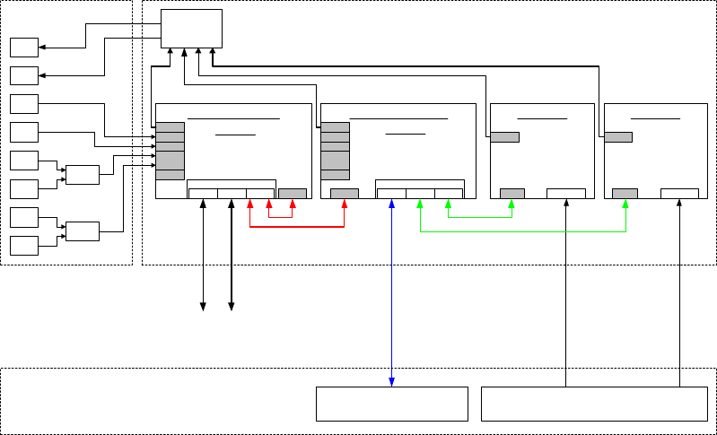
The following diagrams show the hardware components of the computer system for the various
machine types:
Station computer
COM 294
Hardware components of SIPLACE HF and HF/3 computer system
Monitor
1
Monitor
2
Videomux
Keyboar
d 1
Keyboar
d 2
Maus
1
Maus
2
Y-Key
Y-Mouse
Tou ch
screen 1
Tou ch
screen 2
Control unit
Local control / peripherals
(Axes, I/O, component tables, PCB
conveyor)
Camera systems
(PCB camera, component camera RV head,
IC camera Twin Head, FC camera and coplanarity)
SIPLACE LAN
(Line)
Customer LAN
(GEM)
Machine
6 - HubLAN 3
LAN 1
VGA
COM 1
COM 2
KBD /
Mouse
Simicro CPU 076
PII I 866 MHz, 192 MB
6 GB HD , FD, CD
USB
LAN 2
Machine controller
2 x COM352 oder COM354
LAN 1
VGA
COM 1
COM 2
KBD /
Mouse
USB
CAN
VISION 1
4 x camera
HS3L
ICOS
MVS340
VISION 2
4 x camera
HS3L
ICOS
MVS340
HS3L HS3L
Simicro CPU 076
PII I 566 MHz, 64 MB
6 GB HD, FD, CD
VGA VGA
Fig. 3-1: Hardware components of the computer system for the SIPLACE HF series